messages at the same time on the same aerial. Subsequently to the date of the above-mentioned demonstration of multiplex wireless telegraphy by Mr. Marconi, an exhibition of a similar nature was given by Professor Slaby in a lecture given in Berlin on December 22, 1900.[1]
Both the above described syntonic systems of Mr. Marconi and Dr. Slaby are 'earthed' systems, but arrangements for syntonic telegraphy have been devised by Sir Oliver Lodge and Professor Braun, which are 'non-earthed.'
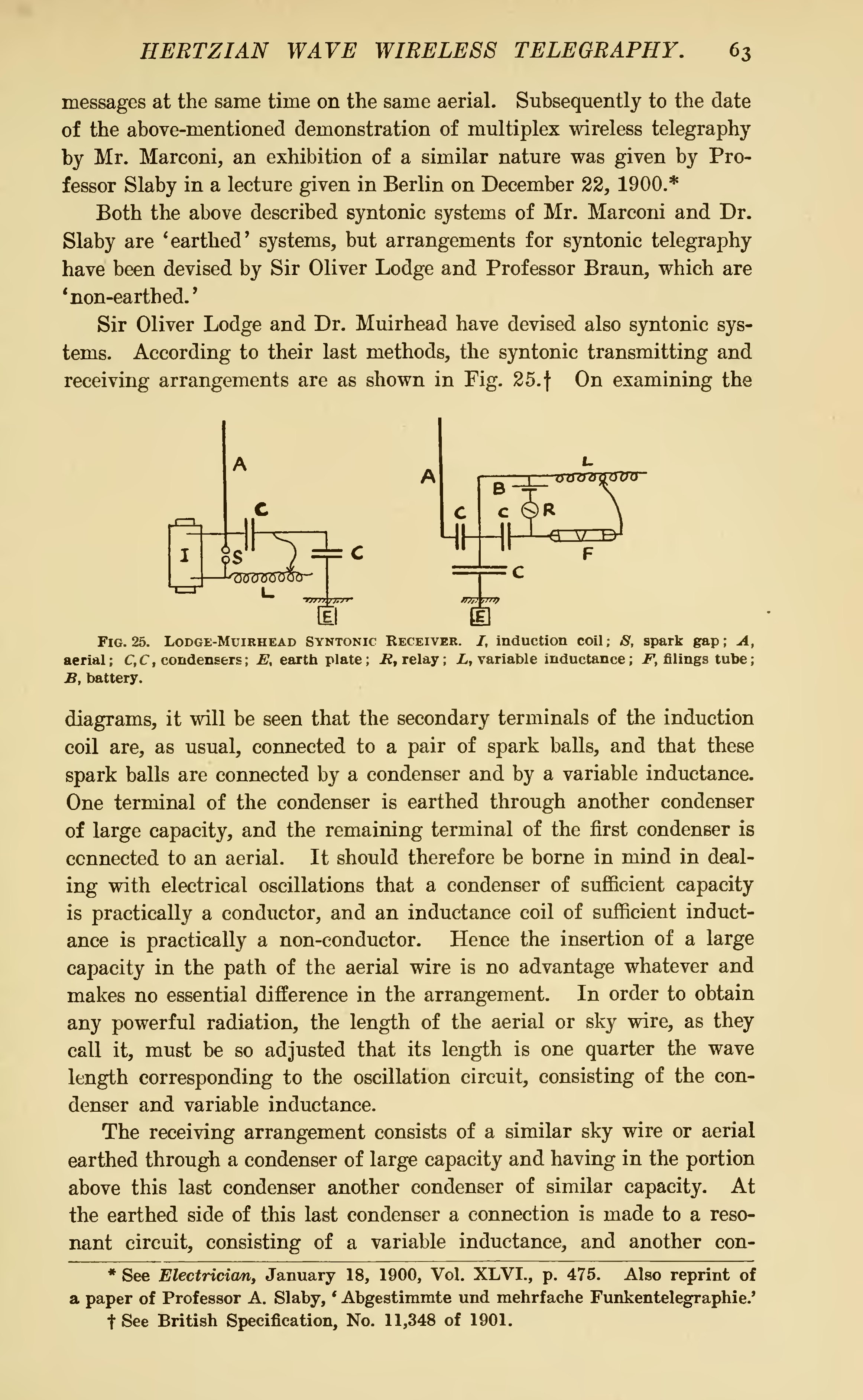
Sir Oliver Lodge and Dr. Muirhead have devised also syntonic systems. According to their last methods, the syntonic transmitting and receiving arrangements are as shown in Fig. 25.[2] On examining the

Fig. 25. Lodge-Muirhead Syntonic Receiver. I, induction coil; S, spark gap; A, aerial; C,C, condensers; E, earth plate; R, relay;L, variable inductance; F, filings tube; B, battery.
diagrams, it will be seen that the secondary terminals of the induction coil are, as usual, connected to a pair of spark balls, and that these spark balls are connected by a condenser and by a variable inductance. One terminal of the condenser is earthed through another condenser of large capacity, and the remaining terminal of the first condenser is connected to an aerial. It should therefore be borne in mind in dealing with electrical oscillations that a condenser of sufficient capacity is practically a conductor, and an inductance coil of sufficient inductance is practically a non-conductor. Hence the insertion of a large capacity in the path of the aerial wire is no advantage whatever and makes no essential difference in the arrangement. In order to obtain any powerful radiation, the length of the aerial or sky wire, as they call it, must be so adjusted that its length is one quarter the wave length corresponding to the oscillation circuit, consisting of the condenser and variable inductance.
The receiving arrangement consists of a similar sky wire or aerial earthed through a condenser of large capacity and having in the portion above this last condenser another condenser of similar capacity. At the earthed side of this last condenser a connection is made to a resonant circuit, consisting of a variable inductance, and another con-
