Popular Science Monthly
��m\
��half lime cask and place it over the center of the bottom of the larger one. Mark around it with a pencil and saw out the resulting disk with a keyhole saw. Fit the lime cask in this opening and nail it securely in place. Arch over the bottom of the large cask and build up around the smaller one with a somewhat richer mixture of cement, about I part cement to 2 parts sand and 2 parts stone. In rounding over the edge of the large cask do not spread the cement less than 2 in. thick at any point.
For a cover, make a mold by nailing a barrel hoop around the edge of a barrel- head; lay in a few pieces of scrap wire, etc., to act as binders and pour in a 2 to 1 mix- ture of cement and sand. Insert an iron ring in the center for a handle. Allow this to set a week before removing the mold. After all has hardened at least two weeks fill in and cover with earth. Such a cess- pool has given good service for nearly six years. — L. B. Robbins.
��Pedal-Operated Brake for a Belt- Driven Motorcycle
THE only brake that can be used on a belt-drive motorcycle is the friction clutch in the rear hub controlled by the starting ped- als. Just to be more up- to-date I ap- / ,^S=====^ plied the at- / /x^\io7 tachment / //^ nd stop ^ shown in the
���A sliding dog on a motor- cycle frame for a pedal brake
��accompanying illustration to operate this brake with a foot-pedal. The main support of the brake is mounted on the frame-brace so that it will move freely. The wire to the foot- lever is attached to the extension on the dog, so that when pressure is applied to the foot-lever the lower part of the dog catches in the chain. The roller prevents the chain from pushing away from the dog. After the dog slips over a link-pin it cannot go farther. As the foot-pedal is pressed down the whole attachment moves forward on the frame-brace, pulling the chain back- ward and setting the clutch-brake. When the foot releases the pedal-lever the spring pushes the dog and support back.
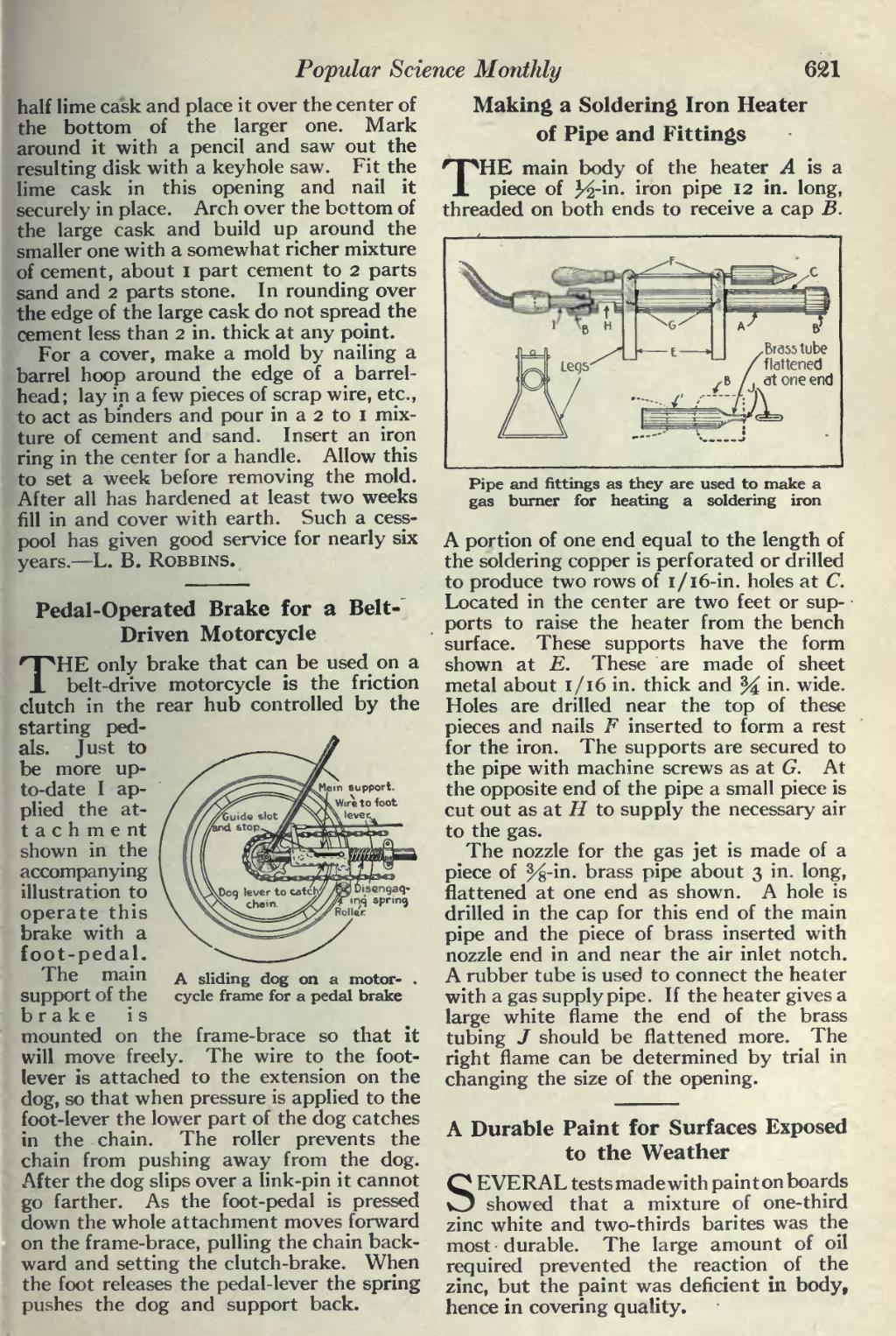
��Making a Soldering Iron Heater of Pipe and Fittings
THE main body of the heater A is a piece of J^-in. iron pipe 12 in. long, threaded on both ends to receive a cap B.
���Pipe and fittings as they are used to make a gas burner for heating a soldering iron
A portion of one end equal to the length of the soldering copper is perforated or drilled to produce two rows of 1/16-in. holes at C. Located in the center are two feet or sup- ports to raise the heater from the bench surface. These supports have the form shown at E. These are made of sheet metal about 1/16 in. thick and % in. wide. Holes are drilled near the top of these pieces and nails F inserted to form a rest for the iron. The supports are secured to the pipe with machine screws as at G. At the opposite end of the pipe a small piece is cut out as at H to supply the necessary air to the gas.
The nozzle for the gas jet is made of a piece of ^8-in. brass pipe about 3 in. long, flattened at one end as shown. A hole is drilled in the cap for this end of the main pipe and the piece of brass inserted with nozzle end in and near the air inlet notch. A rubber tube is used to connect the heater with a gas supply pipe. If the heater gives a large white flame the end of the brass tubing / should be flattened more. The right flame can be determined by trial in changing the size of the opening.
��A Durable Paint for Surfaces Exposed to the Weather
SEVERAL tests made with paint on boards showed that a mixture of one-third zinc white and two-thirds barites was the most durable. The large amount of oil required prevented the reaction of the zinc, but the paint was deficient in body, hence in covering quality.
�� �