464
��Popular Science Monthly
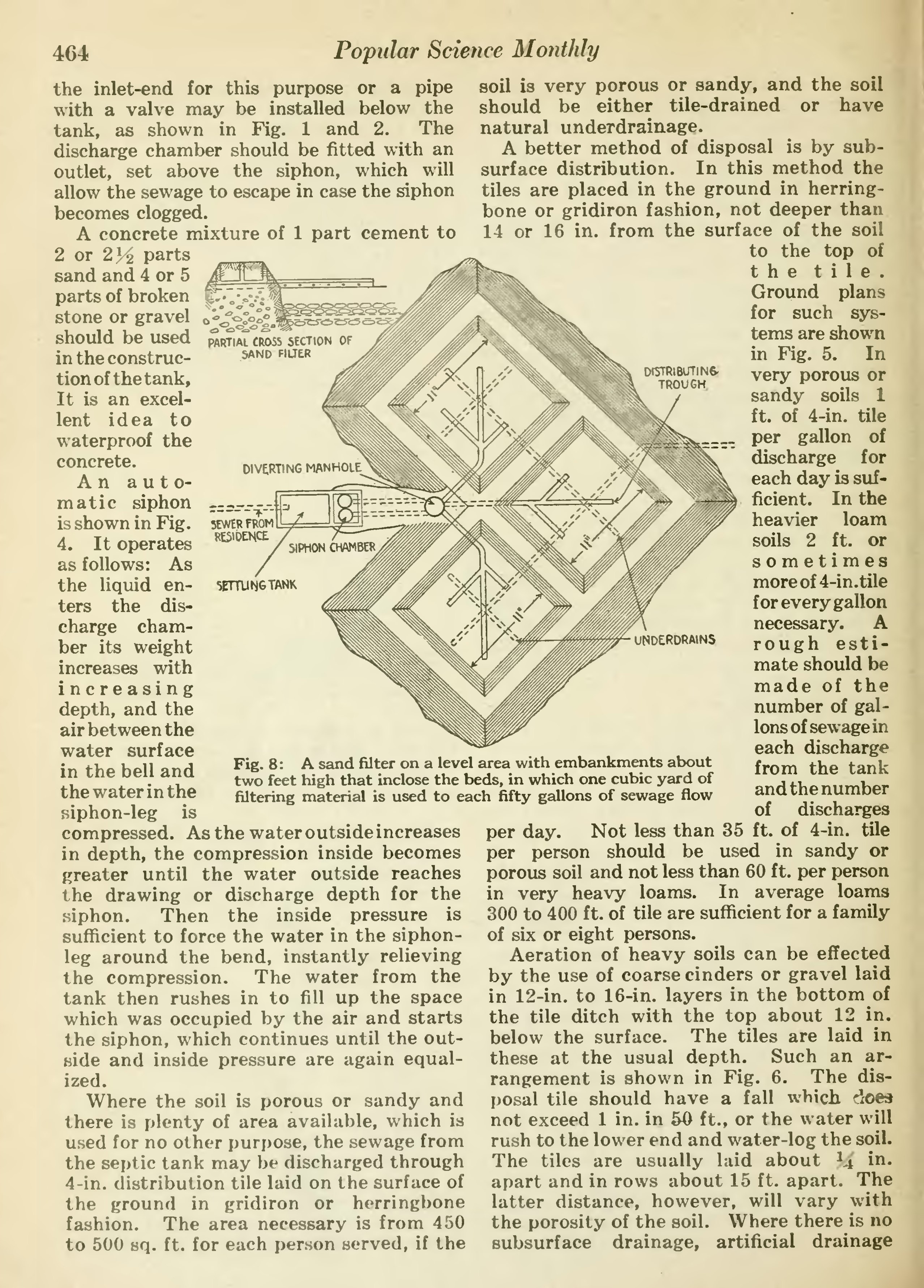
��5EWER FROM RESIDENCE
��5ErrUNGTANK
��the inlet-end for this purpose or a pipe with a valve may be installed below the tank, as shown in Fig. 1 and 2. The discharge chamber should be fitted with an outlet, set above the siphon, which will allow the sewage to escape in case the siphon becomes clogged.
A concrete mixture of 1 part cement to 2 or 2]i parts sand and 4 or 5 parts of broken stone or gravel should be used in the construc- tion of the tank, It is an excel- lent idea to waterproof the concrete.
An auto- matic siphon is shown in Fig. 4. It operates as follows: As the liquid en- ters the dis- charge cham- ber its weight increases with increasing depth, and the air between the water surface in the bell and the water in the siphon-leg is compressed. As the water outside increases in depth, the compression inside becomes greater until the water outside reaches the drawing or discharge depth for the siphon. Then the inside pressure is sufficient to force the water in the siphon- leg around the bend, instantly relieving the compression. The water from the tank then rushes in to fill up the space which was occupied by the air and starts the siphon, which continues until the out- side and inside pressure are again equal- ized.
Where the soil is porous or sandy and there is plenty of area available, which is used for no other purpose, the sewage from the septic tank may be discharged through 4-in. distribution tile laid on the surface of the ground in gridiron or herringbone fashion. The area necessary is from 4 .SO to 500 sq. ft. for each person served, if the
��DISTRlBUTINS- TROUGH.
���UNDERDRA1N5
��Fig. 8 : A sand filter on a level area with embankments about two feet high that inclose the beds, in which one cubic yard of filtering material is used to each fifty gallons of sewage flow
��soil is very porous or sandy, and the soil should be either tile-drained or have natural underdrainage.
A better method of disposal is by sub- surface distribution. In this method the tiles are placed in the ground in herring- bone or gridiron fashion, not deeper than 14 or 16 in. from the surface of the soil
to the top of t h e t i 1 e . Ground plans for such sys- tems are shown in Fig. 5. In very porous or sandy soils 1 ft. of 4-in. tile per gallon of discharge for each day is suf- ficient. In the heavier loam soils 2 ft. or sometimes moreof4-in.tile for every gallon necessary. A rough esti- mate should be made of the number of gal- lons of sewage in each discharge from the tank and the number of discharges per day. Not less than 35 ft. of 4-in. tile per person should be used in sandy or porous soil and not less than 60 ft. per person in very heavy loams. In average loams 300 to 400 ft. of tile are sufficient for a family of six or eight persons.
Aeration of heavy soils can be effected by the use of coarse cinders or gravel laid in 12-in. to 16-in. layers in the bottom of the tile ditch with the top about 12 in. below the surface. The tiles are laid in these at the usual depth. Such an ar- rangement is shown in Fig. 6. The dis- posal tile should have a fall which does not exceed 1 in. in 50 ft., or the water will rush to the lower end and water-log the soil. The tiles are usually laid about J4 i^- apart and in rows about 15 ft. apart. The latter distance, however, will vary with the porosity of the soil. Where there is no subsurface drainage, artificial drainage
�� �
