SHIPBUILDING. When ships were built of wood and propelled by sails their possible size and proportions were limited by the nature of the structural material, while the type of structure had been evolved by long experience and was incapable of any radical modification. Speed depended so much on circumstances independent of the design of the vessel, such as the state of the wind and sea, that it was impossible to include a definite speed over a voyage or measured distance as one of the essential requirements of a design; and the speed actually obtainable was low even under the most favourable conditions when judged by modern standards. Stability depended principally on the amount of ballast carried, and this was determined experimentally after the completion of the vessel. Under these conditions there was no room for any striking originality of design. One vessel followed so closely on the lines of another, that the qualities of the new ship could be determined for all practical purposes by the performance of an almost identical vessel in the past. The theoretical science of shipbuilding, the object of which is to establish quantitative relations between the behaviour and performance of the ship and the variations in design causing them, was generally neglected.
With the introduction of iron, and later of steel, as a structural material for the hulls of ships, and of heat engines for their propulsion, the possible variation of size, proportions and propelling power of ships was enormously increased. In order to make the fullest use of these new possibilities, and to adapt each ship, as closely as may be, to the special purpose for which it is intended, theoretic knowledge has become of paramount importance to the designer. He has been forced to investigate closely those branches of the abstract physical sciences that bear specially on ships and their behaviour, and these mathematical and experimental investigations constitute the study of Theoretical Shipbuilding. It embraces the consideration of problems and questions upon which the qualities of a ship depend and which determine the various features of the design, having regard to the particular services that the ship will be required to perform; i.e. the requirements that must be fulfilled in order that she may make her various passages economically and with safety in all conditions of wind and sea, the best form for the hull with regard to the resistance offered by the water and the engine power requisite in order to attain the speed desired, the nature of waves and their action upon the ship, and the structural arrangements necessary in order that she may be sufficiently strong to withstand the various stresses to which she will be subjected. The determination of the most suitable dimensions to fulfil certain conditions involves the consideration of a different set of circumstances for almost every service; and here the experience gained in vessels of similar type, together with the known effect of modifications made to fulfil new conditions of each particular design, can be used as a guide. The requirements of economical working, safety, &c., determine the length, breadth, depth and form. The length has a most important bearing on the economy of power with which the speed is obtained; and on the breadth, depth and height of side, or freeboard, depend to an important degree the stability and seaworthiness of the vessel.
While, however, the importance to the ship designer of mathematical theories based on first principles and experiment can hardly be overrated, it should be observed that the circumstances and conditions postulated are invariably much less complex than those which surround actual ships. The applicability of the theories depends on the closeness with which the assumed circumstances are realized in practice. The ultimate guide in the design of new ships must, therefore, still remain practical experience. To this experience theory is a powerful assistance, but can by no means replace it.
Theoretical Shipbuilding
Stability.
When a ship floats at rest in still water, the forces acting upon her must be in equilibrium. These consist of the weight of the ship acting vertically downwards through its centre of gravity and the resultant pressure of the water on the immersed hull. If the ship be supposed removed and the cavity thus formed filled with water, then, since this volume of water Equilibrium.is in equilibrium under the same system of fluid pressures, the resultant of these pressures must be equal and opposite to the weight of the water in the cavity and will therefore act vertically upwards through the centre of gravity of this portion of water. Defining the weight of water displaced by the ship as the displacement, and its centre of gravity as the centre of buoyancy, it is seen that the fundamental conditions for the equilibrium of a ship in still water are (a) that the weight of the ship must be equal to the displacement, and (b) that its centres of gravity and buoyancy must be in the same vertical line.
A floating ship is always subject to various external forces disturbing it from its position of equilibrium, and it is necessary to investigate the stability of such a position, i.e. to determine whether the ship, after receiving a small disturbance, will tend to return to its former position, in which case its equilibrium is termed stable, or whether, Stability of equilibrium. on the other hand, it will tend to move still farther from the original position, when the equilibrium is termed unstable. The intermediate case, when the ship tends to remain in its new position, is a third state of equilibrium, which is termed neutral.
Of the modes of disturbance possible, it is evident that a bodily movement of the ship in a horizontal direction or a rotation about a vertical axis will not affect the conditions of equilibrium; the equilibrium is also stable for vertical displacements of a ship. The remaining movements, viz. rotations about a horizontal axis, can be resolved into rotations in which the displacement is unaltered, and vertical displacements, the effect of the latter being considered separately. Of the various horizontal axes about which a ship can rotate two are of particular importance, viz. (1) an axis parallel to the longitudinal plane of symmetry, (2) an axis at right angles to this plane, both axes being so chosen that the displacement remains constant; the stability of a ship with reference to rotations about these axes is known as the transverse stability and the longitudinal stability respectively. In the following account the consideration of stability is confined at first to these two cases; the general case of rotation about any horizontal axis whatever being dealt with later.
 |
Fig. 1. |
Let fig. 1 represent a transverse section of a ship, WL being its water line when upright, and W′L′ its water line when inclined to a small angle θ as shown.Transverse stability.
Assuming that the displacement is unaltered, if G be the position of the ship’s centre of gravity and B, B′ the positions of its centre of buoyancy in the upright and inclined positions respectively, the forces acting on the ship consist of its weight W vertically downwards through G and the resultant water pressure equal to W acting vertically upwards through B′. These constitute a couple of moment W×GZ where Z is the foot of the perpendicular from G on to the vertical through B′; the direction of the couple as drawn in the figure is such as would cause the ship to return to its original position, i.e. the equilibrium is stable for the inclination shown.
If M be the intersection of the vertical through B′ with the original vertical, the moment of the restoring couple is equal to W×GM sin θ, and GM sin θ is termed the righting lever.
If, by moving weights on board, G be moved to a different position on the original vertical through B, the original position of the ship will remain one of equilibrium, but the moment of stability at the angle of inclination θ will vary with GM. If G be brought to the position G′ above M the moment W×G′Z′ will tend to turn the ship away from the original position. It follows that the condition that the original position of equilibrium shall be stable for the given inclination is that the centre of gravity shall be below the intersection of the verticals through the upright and inclined centre of buoyancy; and the moment of stability is proportional to the distance between these two points.
When the inclination θ is made smaller the point M approaches a definite position, which, in the limit when θ is indefinitely small, is termed the metacentre.
In ships of ordinary form it is found that for 10 to 15 degrees of inclination, the intersection of the verticals through the centres of buoyancy B and B′ remains sensibly at the metacentre M; and therefore within these limits the moment of stability is approximately equal Small inclinations.to W×GM sin θ.
Since the angle on either side of the vertical within which a ship rolls in calm or moderate weather does not usually exceed the limit above stated, the stability and to a great extent the behaviour of a vessel in these circumstances are governed by the distance GM which is known as the metacentric height. The position of G can be calculated when the weights and positions of the component parts of the ship are known. This calculation is made for a new ship when the design is sufficiently advanced to enable these component weights and their positions to be determined with reasonable accuracy; in the initial stages of the design an approximation to the vertical position of G is made by comparison with previous vessels.
 |
Fig. 2. |
The position of the centre of gravity of a ship is entirely independent of the form or draught of water, except so far as they affect the amount and distribution of the component weights of the ship. The position of the metacentre, on the other hand, depends only on the geometrical properties of the immersed part of the ship; and it is determined as follows:
Let WL, W′L′ (fig. 2) be the traces of the upright and inclined water planes of a ship on the transverse plane, B, B′ the corresponding position of the centre of buoyancy; θ the angle of inclination supposed indefinitely small in the limit, and S the intersection of WL and W′L′; join BB′.
By supposition the displacement is unchanged, and the volumes WAL, W′AL′ are equal; on subtracting W′AL it is seen that the two wedges WSW′, LSL′ are also equal. If dx represent an element of length at right angles to the plane of the figure, y1, y2, the half-breadths one on each side at any point in the original water line, so that WS=y1, SL=y2, the areas WSW′, LSL′ differ, from 12y12.θ, 12y22.θ by indefinitely small amounts, neglecting which the volumes of WSW′, LSL′ are equal to ∫12y12θdx and ∫12y22θdx.
Since these are equal we have
;

i.e. the moments of the two portions of the water plane about their line of intersection passing through S are equal. This line is also the axis of rotation, which therefore passes through the centre of gravity of the water plane. For vessels of the usual shape, having a middle line plane of symmetry and floating initially upright, for small inclinations consecutive water planes intersect on the middle line.
Again if g1, g2 are the centres of gravity of the wedges WSW′, LSL′, and v the volume of either wedge, the moment of transference of the wedges v×g1g2 is equal to the moment of transference of the whole immersed volume V×BB′ where V is the volume of displacement.
But v×g1S=moment of wedge WSW′ about S=13∫y13.θ.dx, and v×Sg2=moment of wedge LSL′ about S=13∫y23.θ.dx. Adding, 13∫(y13+y23)θ.dx=v×g1g2=V×BB′. But BB′=M.θ to the same order of accuracy, and 13∫(y13+y23).dx is the moment of inertia of the water plane about the axis of rotation; denoting the latter by I, it follows that BM=I/V; i.e. the height of the metacentre above the centre of buoyancy is equal to the moment of inertia of the water plane about the axis of rotation divided by the volume of displacement. These quantities, and also the position of the centre of buoyancy can be obtained by the approximate methods of quadrature usual in ship calculations, and from them the position of the metacentre can be found.
If the ship is wholly immersed, or if the inertia of the water plane is negligible as in a submarine when diving, BM=O, and the condition for stability is that G should be below B; the righting lever at any angle of inclination is then equal to BG sin θ.
During the process of design the position of the centre of gravity is determined by the disposition of hull material and fittings, machinery, coal and all other movable weights, the position of which is necessarily fixed by other considerations than those of stability; but the height of the metacentre above the centre of buoyancy varies approximately as the cube of the breadth, and any desired value of GM is readily obtained by a suitable modification in the beam.
The metacentric height in various typical classes of ships at “normal load” is as follows:—
| Class of ship. | Approximate GM in Ft. |
| First class battleship and cruiser | 312 to 5 |
| Second and third class cruiser and scout | 2 to 3 |
| Torpedo boat destroyer | 112 to 212 |
| First class torpedo boat | 1 to 112 |
| Steam picket boat or launch | .8 to 112 |
| River gunboat (shallow draught) | 8 to 20 |
| Large mail and passenger steamer | .5 to 2 |
| Cargo steamer | 1 to 2 |
| Sailing ship | 2 to 6 |
| Tug | 112 to 212 |
The metacentric height adopted in steamships is governed principally by the following considerations:—
(a) It should be sufficiently large to provide such a position of G as will give ample stability at considerable angles of inclination and sufficient range.
(b) Where ample stability at large angles is obtained by other means, the stability at small angles, which is entirely due to the metacentric height, should be sufficient to prevent forces due to wind on upper works, movement of weights athwartships, turning, &c., causing large and uncomfortable angles of heel.
(c) It should be sufficient to allow one or more compartments to become opened to the sea, through accidental damage, without risk of capsizing.
(d) It should, if possible, be sufficiently large in the normal condition of the ship to permit the greatest possible freedom in the stowage of a miscellaneous cargo without producing instability.
(e) On the other hand an excessive value causes rapid and uncomfortable rolling among waves.
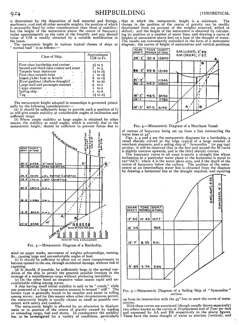
Fig. 3.—Metacentric Diagram of a Battleship.
A ship having small initial stability is said to be “crank,” while one possessed of a large or excessive amount is termed “stiff.” The former type is generally found to be steadier and easier in rolling among waves; and for this reason when other circumstances permit, the metacentric height is usually chosen as small as possible consistent with safety and comfort. The metacentric height is affected by an alteration in displacement or in position of the centre of gravity caused by loading or unloading cargo, fuel and stores. In consequence the stability has to be investigated for a variety of conditions, particularly that in which the metacentric height is a minimum. The change in the position of the centre of gravity can be readily determined from an account of the weights removed, added or shifted; and the height of the metacentre is obtained by calculating its position at a number of water lines, and drawing a curve of heights of metacentre above keel on a base of the draught of water. The results are conveniently embodied in the form of a metacentric diagram; the curves of height of metacentres and vertical positions of centres of buoyancy being set up from a line intersecting, the water lines at 45°.
An image should appear at this position in the text. If you are able to provide it, see Wikisource:Image guidelines and Help:Adding images for guidance. |
- Fig. 4.—Metacentric Diagram of a Merchant Vessel.
Figs. 3, 4 and 5 are the metacentric diagrams for a battleship, a vessel sharply curved at the bilge typical of a large number of merchant steamers, and a sailing ship of “Symondite” (or peg top) section; it will be observed that in the first and second the M curve is slightly concave upwards, and in the third sharply convex.
The buoyancy curve in all cases is nearly a straight line whose inclination at a particular water plane to the horizontal is equal to tan−1Ah/V; where A is the water plane area, and h the depth of the centre of buoyancy below the surface. The position of the metacentre at an intermediate water line is obtained from the diagram by drawing a horizontal line at the draught required, and squaring up from its intersection with the 45° line to meet the curve of metacentres.
An image should appear at this position in the text. If you are able to provide it, see Wikisource:Image guidelines and Help:Adding images for guidance. |
- Fig. 5.—Metacentric Diagram of a Sailing Ship of “Symondite”
section.
With these curves are associated (though usually drawn separately) two others known as the curves of Displacement and of Tons per inch and expressed by AA and BB respectively in the above figures. These have the mean draught of water as abscissa (vertical), and the displacement in tons and the number of tons required to increase the mean draught by 1 in., respectively, as ordinates (horizontal). The ordinate on the curve of displacement at any water line is clearly proportional to the area of the curve of tons per inch up to that water line.
The properties of the metacentric stability at small angles are used when determining the vertical position of the centre of gravity of a ship by an “inclining experiment”; this gives a check on the calculations for this position made in the initial stages of the design, and enables the stability of the completed ship in any condition to be ascertainedInclining experiment. with great accuracy.
The experiment is made in the following manner:—
Let fig. 6 represent the transverse section of a ship; let 𝑤, 𝑤 be two weights on deck at the positions P, Q, chosen as far apart transversely as convenient; and let G be the combined centre of gravity of ship and weights. When the weight at P M is moved across the deck to Q′, the centre of gravity of the whole moves from G to some point G′ so that GG' is parallel to PQ′ (assumed horizontal) and equal to ℎ𝑤/W where ℎ is the distance moved through by P, and W is the total displacement. The ship in consequence heels to a small angle θ, the new vertical through G passing through the metacentre M; also GM=GG′ cot θ=ℎ−𝑤/W cot θ, the metacentric height being thereby determined and the position of G then found from the metacentric diagram. In practice θ is observed by means of plumb bobs or a short period pendulum recording angles on a cylinder;[1] the weight 𝑤 at P, which is chosen so as to give a heel of from 3° to 5°, is divided into several portions moved separately to Q′. The weight at Q′ is replaced at P, the angle heeled through again observed; and the weight at Q similarly moved to P' where P′Q=ℎ=PQ′, and the angle observed; GM is then taken as the mean of the various evaluations.

Fig. 6.
In the case of small transverse inclinations it has been assumed that the vertical through the upright and the inclined positions of the centre of buoyancy intersect, or, which is the same thing, that the centre of buoyancy remains in the same transverse plane when the vessel is inclined. This assumptionLarge inclinations. is not generally correct for large transverse inclinations, but is nevertheless usually made in practice, being sufficiently accurate for the purpose of estimating the righting moments and ranges of stability of different ships, calculated under the same conventional system; this is all that is necessary for practical purposes.
With this assumption, there will always be a point of intersection (M′ in fig. 7) of the verticals through the upright and inclined centres of buoyancy; and the righting lever is, as before, GZ=GM′ sin θ. In this case, however, there is no simple formula for BM′ as there is for BM in the limiting case where θ is infinitesimal; and other methods of calculation are necessary.
The development of this part of the subject was due originally to Atwood, who in the Philosophical Transactions of 1796 and 1798, advanced reasons for differing from the metacentric method which was published by Bouguer in his Traité du navire in 1746. Atwood's treatment of stability (which was the foundation of the modes of calculation adopted in England until about twenty years ago) was as follows:—
Let WL, W′L′ (fig. 7) be respectively the water lines of a ship when
An image should appear at this position in the text. If you are able to provide it, see Wikisource:Image guidelines and Help:Adding images for guidance. |
- Fig. 7.
upright and inclined at an angle θ, S their point of intersection: B and B′ the centres of buoyancy, 𝑔1 and 𝑔2 the centres of gravity of the equal wedges WSW′, L′SL, and ℎ1, ℎ2 the feet of the perpendiculars from 𝑔1 and 𝑔2 on the inclined water line. Draw GZ, BR parallel to W'L', meeting the vertical through B′ in Z and R.
The righting lever is GZ as before; if V be the volume of displacement, and 𝑣 that of either wedge, then
V × BR=𝑣 × ℎ1ℎ2
also
GZ=BR−BG sin θ;
whence the righting moment or
W×GZ=W𝑣×ℎ1ℎ2V −BG sin θ .


This is termed Atwood's formula. Since BG, V and W are usually known, its application to the computation of stability at various angles and draughts involves only the determination of 𝑣×ℎ1ℎ2. A convenient method of obtaining this moment was introduced by F. K. Barnes and published in Trans. Inst. N.A. (1861). The steps in this method were as follows: (a) assume a series of trial water lines at equal angular intervals radiating from S′ the intersection of the upright water line with the middle line plane; (b) calculate the volumes of the various immersed and emerged trial wedges by radial integration, using the formula
𝑣=12𝑑φ∫𝑟2dx,

where 𝑟, φ are the polar co-ordinates of the ship’s side, measured from S′ as origin, and dx an element of length; (𝑐) estimate the moment of transference of the same wedges parallel to the particular trial water line by the formula
𝑣×ℎ1ℎ2=13cos(φ−φ)𝑑φ∫𝑟3𝑑𝑥,
adding together the moments for both sides of the ship; and (𝑑) add or subtract a parallel layer at the desired inclination to bring the result to the correct displacement. The true water line at any angle is obtained by dividing the difference of volume of the two wedges by the area of the water plane (equal to ∫𝑟𝑑𝑥, for both sides) and setting off the quotient as a distance above or below the assumed water line according as the emerged wedge is greater or less than the immersed wedge. The effect of this “layer correction” on the moment of transference is then allowed.
The righting moment and the value of GZ are thus determined for the displacement under consideration at any required angle of heel.
A different method of obtaining the righting moments of ships at large angles of inclination has prevailed in France, the standard investigation on the subject being that of M. Reech first published in his memoir on the “Construction of Metacentric Evolutes for a Vessel under different Conditions of Lading” (1864). The principle of his method is dependent on the following geometrical properties:—
Let B′, B″ (fig. 8) be the centres of buoyancy corresponding to two water lines W′L′, W″L″ inclined at angles θ, θ+𝑑θ, to the original upright water line WL, 𝑑θ being small; and let 𝑔1, 𝑔2 be the centres of gravity of the equal wedges W′TW″, L′TL″. The moment of either wedge about the line 𝑔1𝑔2 is zero, and the moments of W′L′A and FIG. 8. of W″L″A about 𝑔1𝑔2 are therefore equal; since these volumes are also equal, the perpendicular distances of B′ and B″ from 𝑔1𝑔2 are equal, or B′B″ is parallel to 𝑔1𝑔2.
The projection on the plane of inclination of the locus of the centre of buoyancy for varying inclinations with constant displacement is termed the curve of buoyancy, a portion BB′B″ of which is shown in the figure. On diminishing the angle 𝑑θ indefinitely so that B″ approaches B′ to coincidence, the line B′B″ becomes, in the limit, the tangent to the curve BB′B″, and 𝑔1𝑔2 coincides with the water line W′L′; hence the tangent to the curve of buoyancy is parallel to the water line.
Again, if the normals to the curve at B′, B″ (which are the verticals corresponding to these positions of the centre of buoyancy) intersect at M′, and those at B″, B″′ (adjacent to B″) at M″, and so on, a curve may be passed through M′, M″, . . . , commencing at M, the metacentre. This curve, which is the evolute of the curve of buoyancy, is known as the metacentric curve, and its properties were first investigated by Bouguer in his Traité du Navire. The points M′M″, . . . on the curve are now termed pro-metacentres.
If ρ represent the length of the normal B′M′ or the radius of curvature of the curve of buoyancy at an angle θ, then ρ.𝑑θ = 𝑑𝑠 the length of an element of arc of the B curve. In the limit when dθ is indefinitely small, 𝑑𝑠𝑑θ=ρ. Using Cartesian co-ordinates with B as origin and B𝑦, B𝑧, as horizontal and vertical axes, we have—
| 𝑑𝑦𝑑θ=𝑑𝑠𝑑θcos θ=ρ cos θ, | (1) |
| 𝑑𝑧𝑑θ=𝑑𝑠𝑑θsin θ=ρ sin θ, | (2) |
whence

and the righting lever GZ =𝑦 cos θ+(𝑧−BG) sin θ.
The radius ρ is (as for the upright position) equal to the moment of inertia of the corresponding water-plane about a longitudinal axis through its centre of gravity divided by the volume of displacement; the integration may be directly performed in the case of bodies of simple geometrical form, while a convenient method of approximation such as Simpson’s Rules is employed with vessels of the usual ship-shaped type. As an example in the case of a box, or a ship with upright sides in the neighbourhood of the water-line, if BG=𝑎 and BM =ρ0, then ρ=ρ0 sec3θ; whence
𝑦=ρ cos θ.𝑑θ=ρ0 tan θ,
𝑧=ρ sin θ.𝑑θ=12ρ0 tan2 θ,
and
GZ=(ρ0−𝑎) sin θ0+12ρ0 tan2 θ.sin θ;
which relations will also hold for a prismatic vessel of parabolic section. It is interesting to note that in these cases if the stability for infinitely small inclinations is neutral, i.e. if p0=a, the vessel is stable for small finite inclinations, the righting lever varying approximately as the cube of the angle of heel.
The application of the preceding formulae to actual ships is troublesome and laborious on account of the necessity for finding by trial the positions of the inclined water-lines which cut off a constant volume of displacement. To avoid this difficulty the process was modified by Reech and Risbec in the following manner z-Multiply equations (1) and (2) by V.dθ, V being the volume of displacement; we then have—
| 𝑑(V𝑦)=I cos θ.𝑑θ, | (3) |
| 𝑑(V𝑧)=I sin θ.𝑑θ, | (4) |
where I is the moment of inertia of the inclined water-line about a longitudinal axis passing through its centre of gravity. These formulae have been obtained on the supposition that the volume V is constant while θ is varying; but by regarding the above equations as representing the moments of transference horizontally and vertically due to the wedges, it is evident that V may be allowed to vary in any manner provided that the moment of inertia I is taken about the longitudinal axis passing through the intersection of consecutive water-lines. In particular the water-lines may all be drawn through the point of intersection of the upright water-line with the middle line, and the moments of inertia are then equal to 13∫𝑟3𝑑𝑥 for both sides of the ship, 𝑟 being the half-breadth along the inclined water-line; the increase in volume is the difference between the quantity ∫𝑑θ∫12𝑟2𝑑𝑥 for the two sides of the ship.
If Vα, V0 be the volumes of displacement at angles α and θ respectively,
| Vα−V0=dθ[12𝑟2𝑑𝑥 difference] |
(5) |


and substituting in (3) and (4) and integrating
| Vα𝑦=dθ[13𝑟2𝑑𝑥 sum]sin θ |
(6) |
| Vα𝑧=dθ[13𝑟2𝑑𝑥 sum]cos θ |
(7) |
On eliminating Vα in (5), (6) and (7), 𝑦 and 𝑧 can be found.
This is repeated at different draughts, and thus Vα, 𝑦 and 𝑧 are determined at a number of draughts at the same angle, enabling curves of 𝑦 and 𝑧 to be drawn at various constant angles with V for an abscissa; from these, curves may be obtained for 𝑦 and 𝑧 with the angle α as abscissa for various constant displacements; GZ being equal to
𝑦 cos α+(𝑧−𝑎) sin α.
From the foregoing it is evident that the elements of transverse stability, including the co-ordinates of the centre of buoyancy, position of pro-metacentre, values of righting lever and righting moment. depend on two variable quantities—the displacement and the angle of heel. The righting lever GZ is in England selectedCurve of stability. the most useful criterion of the stability, and, after being evaluated for the various conditions, is plotted in a form of curves—(a) for various constant displacements on an abscissa of angle of inclination, (b) for a number of constant angles on an abscissa of displacement.

Fig. 9.—Cross Curves of Stability of a Battleship.
These are known as curves of stability and cross curves of stability respectively; either of these can be readily constructed when the other has been obtained; which process is utilized in the method now almost universally adopted for obtaining GZ at large angles of inclination, a full description being given in papers by Merrifield and Amsler in Trans. I.N.A. (1880 and 1884). The procedure is as follows:
1. The substitution of calculations at constant angle for those at constant volume. A number of water-lines at inclinations having a constant angular interval (generally 15°) are drawn passing through the intersection S′ of the load water-line with the middle line on the body plan. Other water-lines are set off parallel to these at fixed distances above or below the original water-line passing through S′.
2. The volumes of displacement and the moments about an axis through S′ perpendicular to the water-line are determined for each draught and inclination by means of the Amsler-Laffon integrator, the pointer of this instrument being taken in turn round the immersed part of each section.
Fig. 10.—Curves of Stability of a Battleship.
3. On dividing the moments by the corresponding volumes, the perpendicular distance of the centre of buoyancy from the vertical through S′ is obtained, i.e. the value of GZ, assuming G and S′ to coincide.
4. For each angle in turn “cross curves” of GZ are drawn on a base of displacement. 5. From the cross curves, curves of stability on a base of angle of inclination can be constructed for any required displacement, allowance being made for the position of G by adding to, or subtracting from, each ordinate, the quantity GS′ sin α according as G is below or above S′.
An image should appear at this position in the text. If you are able to provide it, see Wikisource:Image guidelines and Help:Adding images for guidance. |
Fig.11.—Curves of Stability of a Merchant Vessel.
A typical set of cross curves of stability for a battleship of about 18,000 tons displacement is shown in fig. 9. It will be observed that the righting levers decrease with an increase of displacement; and this is a general characteristic of the cross curves for ships of ordinary form. The additional weights that constitute the difference between light and deep load (i.e. cargo, coal, stores and water) are generally placed low down, and thus the position of the centre of gravity is usually lower when loaded than when light, causing an increase of stability which frequently more than compensates for the loss of stability indicated by the cross curves.
The stability curves for the same vessel are reproduced in fig. 10. It is customary in warships to draw separate curves for three conditions: (a) normal load, i.e. fully equipped with bunkers about half full, and reserve feed tanks empty; (b) deep load with all bunkers and tanks full; (c) light with all coal, water (except in boilers), ammunition, provisions and consumable stores removed.
An image should appear at this position in the text. If you are able to provide it, see Wikisource:Image guidelines and Help:Adding images for guidance. |
Fig. 12.—Curves of Stability of a Box-shaped Vessel showing the influence of, beam and freeboard.
The curves for a cargo or passenger ship are generally drawn for the condition when light, when full laden with assen ers or with a homogeneous cargo, and sometimes for an intermediate condition; typical curves are given in fig. 11.
Stability curves are obtained on the assumptions—
1. That all openings in the upper deck, forecastle and poop (if any) are covered in and made watertight; and the buoyancy of any erections above these decks is generally neglected.
2. That the side of the ship is intact up to the upper deck, all side scuttles, ports or other openings being closed.
3. That all weights in the ship are absolutely fixed.
4. That no changes of trim occur during the inclination.
In some cases curves are drawn (a) with forecastle and poop intact, (b) with these thrown open to the sea, the latter condition being more commonly considered.
The slope of the stability curve for small angles, the maximum righting lever with the angle at which it occurs, and the range or the inclination at which the stability vanishes are of particular interest, inasmuch as the curve depends principally on these features; and the effect on them, particulars of variation of freeboard,” breadth and position of centre of gravity, is considered below.
An image should appear at this position in the text. If you are able to provide it, see Wikisource:Image guidelines and Help:Adding images for guidance. |
- Fig. 13.—Curves of Stability of “Monarch” and “Captain.”
The stability curve AA (fig. 12) is drawn for a box-shaped vessel of draught 10 ft., freeboard 10 ft. and beam 30 ft.; with C.G. in the water-plane. The curves EE, FF, GG are drawn for the same vessel, but with freeboard altered to 1212, 712 and 5 ft. respectively; it will be observed that freeboard has no influence on the stability at small angles, but has a marked effect on the range and maximum righting lever. An increase of freeboard is generally accompanied by a rise in the position of the centre of gravity; this is not included in the curves, but would actually reduce the stability to. some extent. The effect of freeboard on the range and on the safety of ships is also illustrated by a comparison between the curves of stability (fig. 13) of the armoured turret ships “Monarch” and “Captain,” the latter of which was lost at sea in 1870. These vessels were similar in construction and dimensions except that the freeboard of the “Monarch” was 14′ 0″ and that of the “Captain” 6′ 6″; the smaller freeboard of the “Captain” was associated with a slightly lower position of the centre of gravity and a greater metacentric height. The stability curve of the “Captain” in consequence rises rather more steeply than that of the “Monarch” up to about 14° when the deck edge is immersed; the righting lever then rapidly declines, and vanishes at 5412°, in contrast to, the “Monarch’s,” where the maximum righting lever is doubled and range augmented 1.3 times by the additional freeboard. For the influence of the' range in enabling a ship to withstand a suddenly applied force see “Dynamical Stability.”
An image should appear at this position in the text. If you are able to provide it, see Wikisource:Image guidelines and Help:Adding images for guidance. |
- Fig. 14.—Curves of Stability of a Steam Yacht showing effect
- of variation in height of centre of gravity.
Again, for the box-shaped vessel previously considered, if the breadth is modified successively from 30 ft. to 35, 25 and 20 ft., other features remaining unaltered, the curves of stability then obtained are represented by BB, CC and DD in fig. 12. It is seen that alteration in beam affects principally the stabilityEffect of beam. levers at moderate angles of inclination, while at 90° inclination the curves all intersect. Since at small angles GZ=GM.θ (in circular measure) approximately, the initial slope of the curve is proportional to GM, and the tangent to this curve at the origin can be drawn by settinog by the value of GM as an ordinate to an angle of one radian (57.3°) as abscissa, and joining the point to the origin. (See figs. 10 and 11.) The height of the meta centre above the centre of buoyancy will, caeteris paribus, vary with the cube of the breadth, and an increase of beam will result in a large increase of stability at moderate angles.
Finally the effect of an alteration in the vertical position of the centre of gravity is illustrated by the three stability curves of a steam yacht in fig. 14, where the centre of gravity is successively raised 1 ft. In the condition corresponding to the fourth and lowest curve, the GM is negative (−.2 ft.)Effect of position of C.G. and so also are the righting levers up to 15° when the curve crosses the axis; from 15 to about 52° the GZ is positive, but above that value it again becomes negative. In this case the stability is unstable at the upright position, and the ship will roll to an angle of 15° on either side where the equilibrium is stable. This peculiarity is not uncommon in merchant steamers at light draught. Ample stability at large angles and good range is provided in such cases by high freeboard; but, apart from any considerations of safety, Water ballast is used to lower the centre of gravity to a sufficient extent to avoid excessive tenderness.
The properties of the loci of centres of buoyancy and of prometacentres were fully investigated by Dupin in 1822, including also the surfaces into which these curves develop when admitting inclinations about transverse and “skew” axes. It has been shown that the tangent to the curve of buoyancyGeometrical properties. at any point is parallel to the corresponding water-line; and assuming that the ship is only free to turn in a plane perpendicular to the axis of inclination, the positions of equilibrium are found by drawing from the centre of gravity all possible normals to the buoyancy curve, or equally, all possible tangents to its evolute, the metacentric curve, since the condition to be satisfied is, that the centres of gravity and buoyancy shall lie in the same vertical. Again, when the curve of statical stability crosses the axis, making an acute positive angle as at P in fig. 14, the values of GZ on either side of P are such as to tend to move the ship towards the position at P, and the equilibrium at P is stable. Similarly, when the curve crosses the axis “negatively,” as at the origin and Q, the equilibrium is unstable. Since the angle of intersection cannot be either positive or negative twice in succession, on considering rotation in one direction only, it follows that positions of stable and unstable equilibrium occur alternately and the total number of positions of equilibrium is even.
An image should appear at this position in the text. If you are able to provide it, see Wikisource:Image guidelines and Help:Adding images for guidance. |
Fig. 15.—Metacentric, Buoyancy and Flotation Curves of “Serapis.”
The radius of curvature of the curve of buoyancy is equal to I/V, and is always positive. The curve, therefore, has no re-entrant parts or cusps, is continuous and has no sudden changes in direction; parallel tangents (or normals) can be drawn through two points only (corresponding to inclinations separated by 180°), which property is shared by its evolute, the metacentric curve. On the other hand, the moment of inertia I varies continuously with the inclination, attaining maximum and minimum values alternately; and the metacentric curve, therefore, contains a series of cusps corresponding to the values of I when dI=0, which will generally occur at positions of symmetry (e.g. at 0° and 180°), near the angles at which the deck edge is immersed or emerged, and at about 90° and 270°.
The curves of buoyancy and flotation and the metacentric curve for H.M. troopship “Serapis” are shown with reference to the section of the ship in fig. 15, and on an enlarged scale for greater clearness in fig. 16.[2] It will be seen that the metacentric curve contains eight cusps, M1, M2, . . . M8. Assuming the ship to heel to starboard, M1 corresponds to the upright position, M2 to the immersion of the starboard topsides and emersion of the port bilge; M3 corresponds to 90° of heel, M4 to the complete immersion of the deck and the emersion of the starboard bilge. M5 corresponds to the bottom-up position and similarly for M6, M7 and M8. There are also 6 nodes, of which P and Q are on the middle line. By means of those curves, the effect of a rise or fall in the position of the ship’s centre of gravity can readily be traced. The positions of equilibrium correspond- to the normals that can be drawn from G to the buoyancy curve, or equally to the tangents drawn to its evolute the metacentric curve. For stable equilibrium G lies below M, i.e. generally between B and M; and for unstable equilibrium, similarly, B is between G and M. In the ship under consideration, G1 was the actual centre of gravity, and G1M1 corresponds to the upright position of stable equilibrium. As the vessel heels over, equilibrium (this time unstable) is again reached at about 90°, and a third position (stable) is obtained when the vessel is bottom up, G1M5 being then the metacentric height. A fourth (unstable) position is obtained at about 270°, after which the original position G1M1 is reached, the vessel having turned completely round. For this position of G1 therefore, there are four positions of equilibrium, two of which are stable and two unstable; and this is also true for all positions of G between M1 and M5.
If G lies at G4 between M5 and the point P, there are six positions of equilibrium, alternately stable and unstable. If G is below P as at G5, there are two positions of equilibrium of which the upright only is stable.” A self-righting life-boat exactly corresponds to this condition, the vessel being capable of resting only in the original upright position. If G is above Q, on the other hand, as at G3, there are again only two positions of equilibrium, the vessel being unstable when upright. If G is at G2 there are again six positions of equilibrium; the upright position is unstable, but a stable position is reached at a certain angle on either side. This phase is often realised in merchant ships when light, as already stated (vide fig. 14). When G is exactly upon one of the branches of the metacentric curve, the equilibrium is neutral; if it is at M1 the ship is stable for finite inclinations, and if at Q unstable; similarly for M5 (except that the neutral state is then reached, at 180°) and for P.
In all the above cases it will be observed that the positions of stable and unstable equilibrium are equal in number and occur alternately. There are two exceptions:—
1. When the moment of inertia of the water plane changes abruptly so that the B curve receives a sudden change of curvature. This is possible with bodies of peculiar geometrical forms, and two positions of M then correspond to one position of the body; if G lies between them, the equilibrium is stable for inclinations in one direction and tins tab lien for 'those in the opposite direction, and is then termed mixed.
2. When the equilibrium is neutral, this condition may be regarded as the coincidence of two or more positions of equilibrium alternately stable and unstable. The ship may then be either stable, unstable or neutral for finite inclinations; in exceptional cases she may be stable in one direction and unstable in the other, resembling to some extent the condition of “mixed equilibrium.”
Another curve whose properties were originally investigated by Dupin is the curve of flotation F1F2F3 . . (fig. 15), which is the envelope of all the possible water-lines for the ship when inclined transversely at constant displacement. Since, as previously shown, consecutive water-planes intersect on a line passing through their centre of gravity, or, as it is termed, the centre of flotation, the curve of flotation will be the locus of the projections of the centres of flotation on the plane of the figure, which curve touches each waterline.
From consideration of the slope of a ship's side around the periphery of a water-line, Dupin obtained the following expression for ρ, the radius of curvature of the curve of flotation,
ρ′ = fy2 tan α. dsarea of water-planefor both sides,
where ds is an element of the perimeter, α the inclination of the ship's side to the vertical, and y its distance from the longitudinal axis through the centre of flotation. M. Emile Leclert, in a paper read at the Institution of Naval Architects, 1870, proved the e uivalence of the above formula to the two following, which are (known as Leclert's Theorem:
ρ′=ρ+VdρdV and ρ′=dIdV,
where I and V are respectively the moment of inertia of the water plane and the volume of displacement, and ρ is the radius of the curve of buoyancy or B′M′. Independent analytical proofs of the formulae were given in the paper referred to; and (Trans. I.N.A., 1894) a number of elegant geometrical theorems in connexion with stability, given by Sir A. G. Greenhill, include a demonstration of Leclert's Theorem as follows (in abbreviated form):
Let B, B1 (fig. 17) be the centres of buoyancy of a ship in two consecutive inclined positions, and F, F, the corresponding centres of flotation. Draw normals BM, BIM, meeting at the pro-meta centre M, and FC, FiC, meeting at the centre of curvature C. Produce FB, F1B, to meet at O; join OM, MC.
Then BM, CF and B1M, CF, are respectively parallel, and ultimately also BB1 , FF1, ; hence the triangles MBB1, CFF1 are similar and
BMCF=BB1FF1=OBOF,
so that O, M and C are collinear.
An image should appear at this position in the text. If you are able to provide it, see Wikisource:Image guidelines and Help:Adding images for guidance. |
Fig. 17.
If the displacement V be now increased by dV, changing B to B′, and M to M′, then since the added displacement dV may be supposed concentrated at F, B' will lie on OBF, and it may be shown similarly as before that M' lies on OC. Further, considering the transference of moments, BB′×V=BF×dV.
Draw MED parallel to BF, then
dVV=BB′BF=MEMD=M′ECD=dρρ′−ρ;
∴dρdV=ρ′−ρV or ρ′=+VdρdV,
giving Leclert's first expression; also, since ρ = IV,
dIdV=ρ+VdρdV=ρ′,
which is Leclert's second expression for p'.
The value of ρ′ at the upright can be obtained from the meta centric diagram by the following simple construction. Let M and B be the meta centre and the centre of buoyancy for a water-line WL on the metacentric diagram (fig. 18); draw the tangent to the B curve meeting WL at Q, and through Qdraw QR to meet MB and parallel to the tangent to the M curve at M.
Let BP=h, and area of water-line be A. Then
PQ=h cot θ=hVAh=VA;
also
MR=BM−(BP+PR)=ρ−VA (tan θ+tan φ).
If D be the draught,
tan θ+tan φ =dρdD = −A.dρdV,
whence
MR=ρ+VdρdV=ρ′
the curve of flotation being concave upwards if R is below M.
For moderate inclinations from the upright, the buoyancy of the added layer due to a small additional submersion will act through the centre of curvature of the curve a of flotation; this point may be regarded as that at which any additional weight will, onf being placed on a ship, cause no difference to the values of the righting moment at moderate angles of inclination. The curve of flotation, therefore, and its evolute bear similar relations to the increase or decrease of the stability of a ship due to alteration of draught, as the curves of buoyancy and of pro-metacentres do to the actual amount of the stability.
The curve of flotation resembles the curve of buoyancy in that not more than two tangents can be drawn to it in any given direction, but it differs in that its radius of curvature can become infinite or change sign. It contains a number of cusps determined by ρ′=dIdV=O. These occur in an ordinary ship-shape body at positions: (1) at or near the angles at which the deck is immersed or emerged (four in number); and (2) at or near the angles 90° and 270°. There are, therefore, six cusps in the curve ¢ of flotation of an ordinary ship; they are shown in figs. 15 and 16 by the points F2, F3, F4, F6, F7, F8.
The following relations between the curves of buoyancy and of pro-meta centres and the curve of statical stability are of interest, and enable the former curves to be constructed when the latter have been obtained. If GZ′, GZ″ (fig. 19) are the righting levers correspond in to inclinations θ, θ+ dθ, where dθ vanishes in the limit; B′, B″, the centres of buoyancy, metacentre; produce GZ' to meet, B″M′ in U.
Then, neglecting squares of small quantities,
d(GZ′)=Z′U=M′Z′.dθ,
or vertical distance of M′ above G=d(GZ′)dθ.
Also M′B′=M′B″;
hence
Z″B″−Z′B′=MZ′-MZ″=Z″U=GZ′.dθ,
or
GZ=B′Z′dθ,
i.e. the vertical distance (B′Z′) of G over B is equal to ∫GZ.dθ.
It follows that by differentiating the levers of statical stability and finding the slope at each ordinate the vertical distance of M′ over G is obtained, and M′ may be plotted by setting up this value from Z′ above GZ′ drawn at the correct inclination; also that by integrating the curve of statical stability and finding its area up to any angle, the vertical separation of G and B′ is obtained, and B′ may be plotted by setting down this value increased by BG below Z′.
The work done in inclining a ship slowly so as to maintain a constant displacement (and avoid communicating any unnecessary movement or disturbance to the water) is given by the expression where M is the moment resisting the inclination. This may be writtenDynamical stability.


and it has been shown above that this is equal to the weight multiplied by the vertical separation of the centres of gravity and buoyancy. This is otherwise evident since the work is the sum of that done against the forces acting on the ship, viz. the weight and the buoyancy; these are respectively equal to W×rise of G, and W×fall of B, giving the value W.(Z′B′−BG) as before.
The dynamical stability of a ship at any angle is defined as the work done in inclining the ship from the upright position; and its value is conveniently obtained by integrating the curve of statical stability as stated above. The dynamical stability can thus be calculated at various angles and a curve obtained, whose ordinates represent work done in foot-tons. The curve of dynamical stability is drawn for a battleship (normal condition) in fig. 10, and is there shown in relation to the curve of statical stability; it will be seen that the dynamical stability increases continuously until the righting moment vanishes, when it becomes a maximum.
A formula for the dynamical stability of a ship at any angle was given by Canon Moseley in a paper read before the Royal Society in 1850. Experiments on models made under his direction at Portsmouth Dockyard showed that the actual work in quickly inclining to a moderate angle agreed closely with that calculated in the case of a model of circular section; but considerable divergence was obtained with a model of triangular section owing to the motion of the water set up, and also, probably, to the variation in displacement during the roll.
The existence of large righting couples at moderate angles of heel is of greater importance in a sailing ship than in a steamship, since in the former it determines the amount of sail that can be safely carried under known weather conditions and thereby influences the speed. A sailing ship in motion is subjected to the wind-pressures on the sails and the upper works of the ship, and to the water-pressures on the hull. When the ship is in steady motion, these forces are equal and opposite; and, so far as the stability is concerned, it is sufficient to determine the transverse resultant of the wind-pressure on the sails, and its moment, the water-pressure on the hull affecting only the speed and leeway of the ship.
The pressure on the sails depends on their form and area, their position, and the apparent velocity of the wind, i.e. the velocity relative to the ship. The pressure of the wind on the hull is obtainable similarly to that on the sails, but is usually neglected as the heeling moment is small. Experiments have been made to determine the wind-pressure on plates by Dines, Langley, Eiffel, Stanton and others; and the results of the experiments are briefly as follows—
The normal pressure R in pounds on a plate of area A square feet exposed to face normally a wind of velocity V feet per second is given b the formula R=KAV2, where K is a coefficient depending on the form and area of the plate. For a square or circular plate of about 1 sq. ft. in area K is about .0014, corresponding to a pressure of 1 ℔ per sq. ft. at about 16 knots. The coefficient increases slightly for larger dimensions of the plate. It has also been found that a departure from the square or circular form involving an increase in perimeter for the same area causes an increase in the mean pressure. An alteration from the plane to the concave, analogous to the “bellying” of sails, is accompanied by a slight, increase in the pressure per square foot of projected area; but for any large amount of concavity the increase is more than counterbalanced by the decrease in the projected area.
No simple law exists connecting the normal pressure on a plate exposed obliquely to the wind with the angle of incidence; it is found that the results for air exhibit a close agreement with those for water after allowing for the difference of density between the two fluids. At small angles of incidence up to about 20°, or even 40° (varying with the shape of the plate), the pressure varies, directly as the angle; beyond this limit it is slightly diminished, afterwards increasing or decreasing to a value which is almost constant for the remaining angles up to and including 90°. The centre of pressure for oblique impact lies between the leading edge and the centre of gravity of the area. In a plate 1 ft. square, it lies 0.3 ft. from the leading edge at 10° inclination and 0.4 ft. at 30° inclination, gradually approaching the centre of the plate as the angle of inclination is increased. A slight curving or concavity of the plate does not appear to have much influence on the normal component of the wind pressure.
The wind-pressure on the sails of a ship cannot be calculated with any degree of precision because existing information is insufficient to take account of (a) the variety in area and shape of the sails used; (b) the different positions in which the sails may be placed relative to the wind and to each other; and (c) the interference of adjacent sails with each other. On the other hand, conclusions based on these experiments are of value both in assisting in an intelligent appreciation of the effects of changes in the sail areas, sail positions, and in the form of rig, and in forming a comparison between the various qualities of speed, stability and general behaviour of vessels with which experience has been obtained.
The stability of a sailing vessel is usually estimated by assuming all plain sail to be placed in a fore and aft direction and to be subject to a normal pressure of 1 ℔ per sq. ft., corresponding to a wind of about 16 knots. The resultant pressure of the wind is supposed to act through the centre of gravity of the total sail area (termed the centre of ejort). The resultant pressure of the water on the hull, which is equal and o posite to the wind-pressure, is assumed to pass through the centre of) gravity of the area of the immersed middle line plane (termed the centre of lateral resistance). If h be the vertical distance between these points ir1 feet, A the sail area in square feet, and α the angle of heel, the moment causing the heel is (on these assumptions)
Ah2240foot-tons
and the righting moment is approximately
W×GM sin α.
Hence
sin α=Ah2240.W×GM.
The reciprocal of this quantity or
2240.W×GMAh
is a measure of the capability of the ship to stand up under her canvas and is termed the power to carry sail. Its value varies with different sizes and classes of ships and boats. It is relatively small in small boats and small yachts owing to the practicability of reducing the angle of heel by movable ballast; and a low value is also permissible in large yachts on account of their great range of stability. In-boats and yachts it varies from 3 to 4 and in full-rigged sailing ships from 15 to 20.
The stability of sailing vessels at large angles of inclination varies considerably with the class of vessel. In racing yachts and other completely decked sailing boats whose ratios of beam to depth and draught are comparatively small, initial stability is obtained by lowering the centre of gravity with ballast fitted on the keel, and-the range then extends to considerably over 90°; on the other hand, a number of half-decked or open sailing boats immerse their gunwales when inclined to a moderate angle. With reference to this, Mr Dixon Kemp in his Yacht Architecture remarks that the deck edge should not be immersed at an angle of heel less than 20°; some small centre-board boats whose gunwales are awash at 12° or 15° cause anxiety. With full-rigged sailing ships this angle is commonly 20° to 25.
The effect of a sudden gust of wind on a sailing ship is obtained by equating the work done on the ship by the gust to her dynamical stability; and the angle at which this equality holds will be the extreme angle of heel, assuming the ship to be originally upright and at rest. Since the dynamical stability is represented by the area of the statical stability curve it is convenient to represent this angle in relation to this latter curve. The effects of the resistance and inertia of the water and any change of displacement are neglected; the wind-pressure is assumed constant during the roll, in accordance with the results of experiments on oblique lates (the maximum angle of roll being supposed less than 50°); the modification of the pressure due to the motion of the sail is also neglected.
An image should appear at this position in the text. If you are able to provide it, see Wikisource:Image guidelines and Help:Adding images for guidance. |
- Fig 20.
Let OPQ (fig. 20) be the curve of statical stability, the ordinates representing righting moments, and let the heeling couple due to the gust be represented by OS. If N be the extreme angle of heel, draw SPUR parallel to the base, cutting the curve at P, R; and PM, NQ perpendicular. The work done by the wind is the area OSUN and is equal to the dynamical stability of the ship or the area OPQN. Hence the areas OPS, PQU are equal, and the extreme angle of heel is determined by this equality. If P and Q lie on the initial and approximately straight portion of the curve, the extreme angle of heel ON is about twice that of the steady angle OM corresponding to the strength of the gust. The area QUR represents the reserve dynamical stability when the wind is blowing with strength corresponding to OS; the intercepts of the ordinates below SPUR doing work against the force of the wind, leaving the segments above SPR available for absorbing the kinetic energy possessed by the vessel at the position of steady heel PM. As the strength of the gust is increased the points P and Q travel farther along the curve until P′, Q′ are reached, such that the areas P′Q′Q, OTP′ are equal; the vessel will then come momentarily to rest at Q′ and will be in unstable equilibrium, any increase in the wind-pressure causing her to capsize. It follows that a ship sailing in a wind of sufficient strength to cause a moderate angle of heel equal to OM′ will be on the point of capsizing if the wind should happen to drop and afterwards return suddenly with its former force, A more dangerous, though improbable, case in which a gust of wind strikes the ship just as she has completed a roll to windward' can similarly be investigated; it is found that the safe angle of steady heel under this condition is considerably less than that represented by OM′. It thus appears that it is of the-greatest importance that sailing vessels should possess large dynamical stability in order to provide against the risk of capsizing due to fluctuations in the wind-pressure. Although the neglect of the wind and water resistances in the above investigation materially modifies the quantitative results, the general conclusions point to the necessity for sufficient range and freeboard however large the righting levers may be at small inclinations.
The centres of effort and of lateral resistance have not the same longitudinal position, consequently horizontal couple is produced which turns the vessel either into the wind or away from it. In the former condition the vessel is said to be “ardent,” and in the latter to be “slack.” In order that a vessel maybe quick in going about and yet not require too large a helm angle on a straight course, she should be slightly “ardent,” i.e. the true centre of effort should be slightly abaft the true centre of lateral resistance; The assumed and true positions of these centres differ to some extent, and on making allowance for this it is found that in the majority of vessels possessing slight ardency the assumed C.E. lies slightly before instead of abaft the assumed C.L.R. In small sailing boats the points are usually very near together but in a large number of sailing ships, including H.M. sloops, their distance apart is about .05 L, and in yachts' about .02 L, where L is the length.
It may be noted in this connexion that the area of sail spread and the size of the ship are often connected by the coefficient AW23 known as the Driving Power, The, value for small sailing boats and for yachts is about 200, and for- full-rigged sailing ships from 80 to 100 (including plain sail only).
The method of estimating the: righting moment of a ship when inclined from a position of equilibrium through a small angle in the longitudinal plane is exactly analogous to that used in the case of small transverse inclination, and similar propositions are true in both cases, viz.:—
1. Consecutive water-lines intersect about an axis passing through the centre of flotation.
2. The height of the longitudinal meta centre M above the centre of buoyancy is equal to the moment of inertia about this axis divided by the volume of displacement of the ship.
3. The righting moment at any small angle of inclination θ (circular measure) is equal to
W.GM.θ
An image should appear at this position in the text. If you are able to provide it, see Wikisource:Image guidelines and Help:Adding images for guidance. |
Fig. 21.
In fig. 21 let WL be the water-line corresponding to the positions G and B, and conceive a longitudinal movement of a portion of the weights in the ship causing G to move horizontally to G′. If G′ be abaft G the ship will alter trim by the stern until B moves to B′ vertically beneath G′ and the water-line changes to W′L′, intersecting WL at the centre of flotation F.
If L be the length of the ship between the draught marks, the change of trim (WW′+LL′) is equal to L.θ, and the moment changing trim is W.GG′ or W.GM.θ: the change of trim in inches (other linear dimensions being in feet) is therefore
The change of trim due to any horizontal movement of weights is therefore equal to the moment of the shift of weight divided by the quantity
W×GM12×L
which is the moment required to change trim one inch. Since the longitudinal moment of inertia of the Water-plane includes the cube of the length as a factor, the longitudinal BM is usually large compared with BG, and the moment to change trim 1 in. in foot-tons is nearly equal to
which is approximately constant for moderate variations of draught.
If a weight of moderate amount 'w tons be placed at a distance of a feet abaft the centre of flotation F, the bodily sinkage in inches is wT, the moment changing trim by the stern is wa foot-tons, and the change of trim is therefore waM where T is the “tons per inch” and M the moment to change trim 1 in. If b be the distance of F abaft the middle of length, the draughts forward and aft are increased respectively by
w (1T−aM ⋅ L+2b2L)
and
w (1T+aM L−2b2L) inches.
A ship provided with' water-tight compartments is liable to have
water admitted into any of them on account of damage
received, or may require to carry water or other fluid in
bulk as ballast or cargo. The effect of this addition on the LY en d
draught and the stability is therefore of interest. ThereStability when damaged.
are three cases:—
1. When the water completely fills a compartment;
2. When the water partially fills a compartment up to the level of
the water-line, remaining in free communication with the sea; and
3. When a compartment is partially filled with water without any
communication with the sea.
In the first case the water is regarded as a weight added to the ship; the mean sinkage is obtained from the displacement curve, the change of trim from the “moment to change trim,” and the angle of heel from the metacentric diagram, or (for large angles) the cross curves. In general, if the compartment filled is low in the ship, the stability is increased; if high, it is diminished.
In the second case, assume in the first place the compartment to be amidships, so that no heel or change of trim occurs, and to be moderate in siie, so that the sinkage is moderate in amount.
An image should appear at this position in the text. If you are able to provide it, see Wikisource:Image guidelines and Help:Adding images for guidance. |
Fig. 22.
Let ABCD (fig. 22) be such a compartment bounded by; watertight bulkheads sufficiently high to prevent water reaching adjoining compartments. Let the water-lines be WEFL, W′GHL′, before and after bilging; let A, a be the area of the whole water-plane WEFL and of the portion EF within the compartment respectively, in square feet; and let v be the volume contained in EBCF diminished by the volume of any solid cargo in the compartment;, The buoyancy is reduced by ans amount v by bilging, and the amount added through sinking must be equal to the amount so-lost. If x be the sinkage in feet, then
v=x(A−a),
so that the mean sinkage is equal to the buoyancy lost divided by the area of the intact water-plane. In the event of the compartment being so situated as to cause heel and change of trim, the mean sinkage is first determined as above, and the effect of heel and change of trim superposed.
To obtain the heel produced, the position of the centre of flotation for the intact portion of the water-plane is, found, and thence the vertical and horizontal positions of the new centre of buoyancy. are deduced by takingateount of the buoyancy lost through bilging, and then regained by the layer between the two water-planes. The moment of inertia of the intact water-plane is found about an axis through the new centre of flotation and thence the height of the new meta centre M′ determined. The heel θ (assumed small) is found by equating the horizontal shift of B to sin θ× the vertical distance of M′ above G, both being equal to the moment causing heel divided by the displacement.” Tn a similar manner the change of trim is obtained. If the compartment bilged is large so that considerable changes in its area and that of the ship at the water-line result, the sink age and alteration in stability are found by a tentative process, closer approximations to the final water-line being successively made.
An investigation of the stability when bilged at or near the waterline is, of“special importance in warships owing to their liability to damage by gunfire in action, with the consequent opening up of a large number of compartments to the sea. Calculations are made of the sinkage and stability when the unarmoured or lightly armoured parts of the ship are completely riddled; the stability should be sufficient to provide for this contingency.
The third case, where the ship is intact but has compartments partially filled with water or other liquid, is of frequent occurrence. Practical illustrations occur in connexion with the filling and emptying of water-ballast and oil-fuel tanks, and particularly in the case of ships fitted to carry large quantities of oil in bulk.
Let fig. 23 represent the section of a vessel fitted with a tank PQRS partly full of water. Let WL, wl be the upright water-lines
of the vessel and tank, G the centre of gravity of the vessel and
water combined, B the centre of buoyancy of the vessel, and b the
centre of gravity of the Water.,
An image should appear at this position in the text. If you are able to provide it, see Wikisource:Image guidelines and Help:Adding images for guidance. |
Fig. 23.
As the ship is inclined successively through angles θ1, θ2, . . . the centre of buoyancy B moves along the curve of buoyancy to B1, B2, . . . the normals at which are tangential to the metacentric curve M1 M1, . . . those at small angles passin through the meta centre M. If the water in the tank could be kept from moving as the inclination roceeded, G would be fixed in the ship, and the righting levers would be GZ1, GZ;, those at small angles being equal to GM sin θ. Actually, if the inclination be slowly performed, the water-level in the tank changes successively to w1l1, w2l2, . .maintaining a level surface at all times; its centre of gravity moves to b1, b22, . . . thereby causing a corresponding alteration in the combined centre of gravity G. Drawing bn, bn, perpendicular to the verticals through b1, b2, . . and calling w, W the weights of the water and of the water and ship combined, then at the angle θ2 the line of action of the weight of the water w has moved through a distance bn and the righting moment of the ship is diminished by an amount w×br2. It is evident that the movement of the centre of gravity of the water in the tank is the same as would be the movement of the C.B. of a ship having the same form as the tank and water-lines corresponding to wl, w1l1, w2l2, &c. The values of the levers br1, br2. . .can therefore be obtained by a process similar to that used for obtaining the righting levers of the ship; cross curves and thence ordinary stability curves being drawn for various heights of water and inclinations. If θ1 be a small angle of inclination, the line of action of the weight b1m will be such as to pass through the metacentre m corresponding to the water-line wl, and determined by the formula bm=iv where i is the moment of inertia of the water-plane wl about a longitudinal axis through its centre of gravity and v the volume of water contained. The moving weight w at b may therefore be replaced by an equal weight fixed at m, which is the virtual centre of gravity of the water; and the centre of gravity G of ship and water is likewise raised to a virtual position G′ where
GG′=wW⋅bm=vV ⋅ iv=iV.
If the tank contain a fluid of specific gravity p the virtual rise of the centre of gravity is ρiV. The loss of stability at small angles due to the mobility of the water is thus independent of the quantity in the tank, but is proportional to the moment of inertia of its free surface. It is possible for a small quantity of water with an extensive free surface to render a ship unstable in the upright condition; the angle to which this large loss of stability extends depends, however, on the quantity of water in the tank, for the extent of the sideways movement of the centre of gravity G of ship and water is minute if the tank be either nearly empty or nearly full, and the loss of stability at all angles above a small amount will then be inappreciable; the loss at moderate angles is usually a maximum when the tanks are about half full.
The assumption made above, viz. that the ship is inclined so gradually as to maintain a level water surface in the tank, is by no means in accordance with the actual circumstances during rol ing; waves are then set up in the water, causing it to wash from side to side. so that the loss of stability may be either more or less than the amount calculated. To avoid danger of capsizing in still water, large tanks in a ship are filled or emptied in succession as far as possible, so that not more than one or two are partly full at the same time. Water-tight longitudinal partitions are also fitted in wide tanks in order to reduce the moment of inertia of the free surface. On the other hand tanks, partly filled with water, have been fitted and found effective in certain ships in order to reduce the rolling oscillations among waves. (See § Rolling.)
Hitherto the stability of a ship has been considered only with reference to inclinations, about either a longitudinal or transverse axis. These are the only cases which it is necessary to deal with in practice for the purpose of ascertaining the probable qualities as re rds stability of a vessel by comparing the elements (fits stability in the design stage with those of existing ships Whose qualities have been tested by experience. For the exact theoretical consideration of the stability of a ship or any floating body, however, it is necessary to take account of the true line of the action of the buoyancy and not merely of its projection on the plane of inclination. The development of this part of the subject has largely been due to M. Dupin in his Mémoire de la stabilité des corps flottants and to M. Guyou in his Théorie du navire. If a ship is inclined in all possible positions, keeping the displacement constant, the locus of the centre of buoyancy is a closed surface which is known as the surface of buoyancy; the curve of buoyancy for two-dimensional inclinations being, the projection on the plane of 'rotation of the corresponding points on the surface of buoyancy. Similarly the envelope of all the water-planes is defined as the surface of flotation. The stability of a ship in all positions is known when (a) the forms and dimensions of the surface of buoyancy, and (b) the position of the centre of gravity relative to it, have been obtained; the former depends entirely on the geometrical form of the ship and on the constant volume of displacement assumed, and the latter has reference only to the arrangement and magnitude of the component weights of the structure and lading. For an infinitesimal inclination the line joining the centres of buoyancy when upright and inclined is parallel to the water-plane, and the tangent plane to the surface of buoyancy is therefore parallel to the water-plane, i.e. it is horizontal, and the normal to the surface is vertical. If the initial position is one of equilibrium, the centre of gravity must lie on the normal. To determine the effect of a small disturbance from the position of equilibrium, it is necessary, as in the particular inclinations already considered, to find the line of action of the buoyancy for adjacent positions, Le. to trace the normals to the surface of buoyancy. Consecutive normals to this surface will not, in general, intersect; but, from the properties of curvature of surfaces, there are two particular directions of inclination for which adjacent normals to the surface will intersect the original normal, these directions being perpendicular to one another and parallel to the principal axes of the indicatrix of the surface of buoyancy.
An image should appear at this position in the text. If you are able to provide it, see Wikisource:Image guidelines and Help:Adding images for guidance. |
Fig. 24.
If fig. 24 be a plan of the water-plane, Ox1 the axis of inclination passing through O the centre of flotation, Oy and Oz perpendicular axes in and at right angles to the plane of flotation, then, from a consideration of the wedges of immersion and emersion for a small inclination 0, the travel o the centre of buoyancy B becomes:—
θV∬y′2.dx′.dy′ (or BB1, in fig. 24) parallel to Oy
θV∬y′.dx′.dy′ (or—BB1) parallel to Ox
and
12θ2V∬y′2.dx′.dy′ (or B2B′)parallel to Oz.
These may be written:-
θV⋅Ix′; θV⋅P; and θ22V⋅Ix′ respectively
where Ix′ is the moment of inertia of the water-plane about Ox′, and P the product of inertia about Ox', Oy'. If the principal axes of inertia of the water-plane Ox, Oy make an angle ¢ with Ox', Oy', and if, from B as origin, axes Bx, By, Bz are drawn parallel to Ox, Oy, Oz, then the co-ordinates of B' are as follows:—
x= -BIB; cos ¢-BB; sin ¢=%-(P cos ¢>-l, ' sin ¢); y= BB, cos da-BIB; sin ¢=%(I, ,' cos 4:-l-P sin ¢); 0” 1
Z= B2B'=w'Iz .,
Also,
l, ,' = I, cos' ¢>+I, , sin' ¢;
P =(I, - I,) sin ¢ cos ¢; where Ix, Iy, are the principal moments of inertia of the water-plane. Hence
- x = −θV⋅Iy⋅sin φ;
- y = θV⋅Ix⋅cos φ;
- z = 12θ2V(Ixcos φ+Iysin2 φ).
Eliminating θ and φ, the locus of the centre of buoyancy for small inclinations of the ship becomes the elliptic paraboloid—
and the indicatrix is therefore similar and similarly situated to the
momental ellipse of the water-plane and the surface of buoyancy is
everywhere synclastic and concave to all points within it. The
quantities Iy/V and Ix/V are evidently equal to BMx and BMy (referring
to inclinations about Oy and Ox respectively); and the
indicatrix and momental ellipse become
x2 %f- +§ yTjI- =constant.
The angle φ that BB2 (the projection of BB′ on the plane of the indicatrix) makes with xO is given by
- tan φ= -%=-f. cot φ;
hence the direction is conjugate to that of the axis of rotation with respect to the indicatrix.
This is illustrated in fig. 25, where the ellipse shown is the indicatrix; OPx′ the axis of inclination, OQ the conjugate radius, and ORMy′ the perpendicular on the tangent. Draw QN parallel to OM to meet OP. The triangle OMQ is similar to BB1B2; and they can be made equal by giving a suitable value to the constant in the indicatrix equation. In that case QN is the projection on the plane of the figure of the normal to the surface at Bl, and the shortest distance between the normals at B and B1 is equal to ON = MQ =
An image should appear at this position in the text. If you are able to provide it, see Wikisource:Image guidelines and Help:Adding images for guidance. |
FIG. 25.
B1B2 =PθV, since ON or the axis of inclination is perpendicular to them both. Also, the length B'M of the normal at B' intercepted between B' and the foot of the common perpendicular is equal to gg since 0 is the angle between the normals at B and B'; it follows BB I
that B'M'=-f=§ ,
an expression analogous to that obtained before for.the case of small inclinations in the direction of the principal axes of the water plane. It is worthy of note that the radius of curvature p of the normal section of the surface of buoyancy through Oy' is, in general, OM' .
less than BM; the latter being equal to OM22z and ρ being equal to OR22z; ρ is also obtainable by Euler's equation—
1/ρ = cos ... sin φ ...
becoming equal to BM for inclinations about the principal axes. Similarly the radius of curvature of the normal section through Q is, in general, greater than BM.
If the centre of gravity G of the ship is coincident with B, the arm
of the righting couple is OM or ie?—0; and there is also a couple of lever ON or $0 in a perpendicular vertical plane. The resultant couple lies in a plane containing OQ, having a lever equal to OQ or %/i, '=+P= org/ 1, = cos =φ+.1,2 Sin =φ In the general case when G is situated at a distance a above B, the I
righting lever becomes <%—a) 0, and the perpendicular couple is unaltered. The resultant couple can be readily found, but in this case it bears no simple relation to the indicatrix, as before; it may be shown, however, that the plane of the couple is conjugate to the axis of inclination with respect to the confocal ellipse x2 y2
Ei-% a -constant.
V
In the case when GM=O, the ship being in neutral equilibrium for that direction of inclination, the resultant couple is parallel to the axis Ox′, i.e. perpendicular to the plane of the indicatrix.
Numerical values of the metacentric height GM, the angle of obliquity α to the indicatrix referred to axes parallel to Bx, By is Obliquity a or QOM (equal to tan-1PIx′−aVP and the angle φ are given JC' in the following table for a ship whose transverse GM is 4 ft., longitudinal GM 400 ft., and BG 10 ft.:—
| φ | 0° | 1° | 5° | 10° | 20° | 30° | 40° | 50° | 60° | 70° | 80° | 90° |
| GM | 4′ | 4·1 | 7′ | 16 | 50·4′ | 103′ | 168′ | 237 | 300 | 354 | 388 | 400′ |
| α | 0° | 60° | 78·5 | 76·8° | 68·5° | 59° | 49·3° | 39·5° | 29·7° | 19·8° | 9·9° | 0° |
| ψ | 90° | 29·0° | 6·5° | 3·2° | 1·5° | 1·0° | 0·7° | 0·5° | 0·3° | 0·2° | 0·1° | 0° |
The greatest angle of obliquity (α) occurs in this case when φ is about 534° and the plane of the couple is nearly coincident with the middle line plane for all angles of φ greater than about 30°. It follows that if a weight is moved obliquely across the s ip the axis of rotation is approximately longitudinal, except when the line of movement is nearly fore and aft; and in the latter case a small deviation from a fore and aft direction produces a large change in the position of the axis of rotation.
The direction of the axis of rotation is above expressed with reference to the position of the inclining couple in relation to the indicatrix of the surface of buoyancy; as, however, the couple is assumed small, the direction of the axis and the amount of inclination may equally be obtained by resolving the couple in planes perpendicular to the principal axes and superposing the separate inclinations produced by its components. It has been shown above that the positions of uilibrium are found by drawing all possible normals to the surface 2? the buoyancy, and the condition for stability for an inclination in any direction is that the centre of ravity shall lie below the corresponding meta centre. The height of tie meta centre varies with the moment of inertia of the water-p ane about the axis of inclination, and the maximum and minimum heights are associated with the maximum and minimum moments of inertia, which again correspond to inclinations about the least and greatest axes of inertia respectively. If the centre of gravity lies below the lowest position of the meta centre (the transverse meta centre in the case of a ship when upright) the equilibrium is stable for all inclinations, and the condition is referred to as one of absolute stability; if it lies above the highest metacentre, the condition is one of absolute instability; if it lies between the highest and lowest metacentres, the condition is one of relative stability, the ship being stable for inclinations about a certain set of axes, and unstable otherwise.
The foregoing remarks apply to a vessel whose axis of inclination is fixed so that the component couple perpendicular to the plane of inclination is resisted. If, on the other hand, the vessel is free to move in all directions the resultant couple does not in general tend to restore the original position of equilibrium, although the component in the plane of inclination complies with the conditions above stated for absolute stability. If m1 and m2 be the greatest and least values of GM, the ratio of, the component couples perpendicular to and in the plane of inclination, or tan a. (fig. 25), is greatest when
m
tan φ= gi; and then tan a.=;%#. If mg/mi be small, this 1 2
ratio is large, being equal to 4.95 in the numerical example above. In such cases the extent of the movement that can result from a small initial disturbance cannot be readily determined by statical method, but the investigation of the work done in moving the vessel from one position to another appears to meet this difficulty.
This process is employed by M. Guyon in his Théorie du navire, the stability of a shi in any condition being treated throughout from the dynamical standpoint. He proved that:—
1. For changes of displacement, without change in inclination, the potential energy of a system consisting of a floating body and the water surrounding is a minimum when the weight of the body is equal to its displacement.
2. For changes of direction, without change of displacement, the potential energy of the system is equal to the weight of the body, multiplied by the vertical resolute of BG; when this distance is a minimum or a maximum the stability is respectively stable or unstable. A statical proof of this has been given in the two dimensional case.
The potential energy is thus equal to the dynamical stability increased by an arbitrary constant. If from any point B1′ of the surface of buoyancy (fig. 26) a tangent plane be drawn, the perpendicular upon it, GN, is proportional to the potential energy, and the stability of the body is thus the same as that of the surface of buoyancy regarded as a solid capable of rolling on a horizontal plane. The locus of the foot of the perpendicular N is called the “podaire” (shown dotted in the figure)'; this surface resembles the surface of buoyancy in its general shape, and touches it when GB is normal, i.e. at positions of equilibrium B1, B2, B3, B4,; it has the property that a radius GN drawn from G is always vertical when the body is in the position corresponding to N, and has a length proportional to the potential energy.
An image should appear at this position in the text. If you are able to provide it, see Wikisource:Image guidelines and Help:Adding images for guidance. |
Fig. 26.
Fig. 27.
If the ship or body be supposed to move under no external forces, and the effect of any change in the displacement be neglected, the kinetic energy of the system can be expressed by Σmv2/2g, and the total energy by (W×GN)+12g. Σmv2/2; the latter is constant when there are no resistances, and steadil decreases if resistances are in operation. Neglecting resistance, when the body is momentarily at rest, W×GN becomes W.l, where l is a linear quantity; and throughout the motion GN is less than l by 12gWΣmv'2. The effect of resistance is gradually to decrease l or the maximum value of GN; and it may be exhibited graphically by the following conception. imagine a sphere of water, with centre at G, to be origin all entirely within the podaire and then to be capable of expanding until the whole surface is submerged. It will first touch the podaire at the minimum normal, and will then form a~ small lake round it; similar lakes will form later at all other positions of absolute stability. Positions of absolute instability will be touched externally by the sphere, and if the water recede a little, will form 'small islands. 'At positions of relative stability the water will in general divide the surface into two parts meeting at an angle (fig. 27), and become one or the other of the branches XX', YY" according as the size of the sphere is slightly increased or diminished. Let the radius GN to the podaire along the edge of the water be represented by l; from the 'energy equation the radius for any other position of the body moving without external forces is less than l, and the position lies within the lake so bounded. The diminution of l due to resistances has the effect of gradually drying the lake. If the body is originally placed near a position of absolute stability, the small lake on drying will leave-the body in or very near that Position. On the other hand, if the body is placed at rest near a position of absolute instability, the water in drying will necessarily cause the body to move farther and farther from that position. Finally, if moving near a position of relative stability, the y will move freely from side to side until the drying has proceeded so far that separate branches XX' or YY' are obtained; when this occurs, the body will be fenced, as it were, on one side or the other, anchwég oscillate until a position of absolute stability is finally attained.
With regard to the surface of flotation it has been shown that in order that the displacement shall remain constant, consecutive waterlmes must intersect on a line passing through the centre of gravity of the waterline or the centre of flotation. If the inclination take place from a given position in all possible directions, the lines of intersection with the original water-plane will all meet at the centre of flotation, which must, therefore, lie in the envelope of the water-planes, of the surface of flotation. The surface is therefore the locus of the centre of flotation for all possible inclinations. Since the curvature of the curve of flotation, which is the projection of the 'centre of 'flotation for inclinations about an axis perpendicular to the plane of projection, may change sign, the surface can also undergo similar changes in curvature and may be synclastic in certain parts and anti-elastic or saddle-shaped in others.
The relation between the surface of flotation and the stability of the ship is similar to that established in the two dimensional cases, i.e. the projection on the plane of inclination of the curve corresponding to the inclination has a centre of curvature whose height is a measure of the increase or decrease of stability caused b an alteration in displacement; the investigation, however, of the general case and the extension of Leclert's theorem to oblique inclinations contain no features of special -interest or importance.
Rolling of ships.
The action of the waves upon a ship at sea is such as to produce rolling or angular oscillations about a horizontal longitudinal axis, pitching or angular oscillations about a horizontal transverse axis, and heaving or translational oscillations in a vertical direction; also horizontal translations and rotations about a vertical axis which are not generally of an oscillatory character and will not materially affect the rolling. It is convenient when considering rolling to neglect the influence of the other accompanying oscillations, whose effect in most cases is. slight in magnitude although complex in character.
The ship is in the first place conceived to, bevrolling in still water without any resistances operating todiniinish the motion. The equation of motion for moderate angles of inclination, within which the arm of the righting couple is approximately proportional to the angle of heel (i.e. GZ=mX0), is
| (1) |

where ε is the radius of gyration of the ship about the axis of rotation, m the metacentric height, θ the angle of inclination and g the acceleration produced by gravity. From this the time deduced for a single oscillation, from port to starboard, or vice versa, is
| (2) |

showing that the time of oscillation varies directly as the radius of gyration, and inversely as the square root of the metacentric height.
The value of T is generally about 10 seconds in a large Atlantic liner, 7 to 8 seconds in a battleship, and 5 to 6 seconds in second-class cruisers and ships of similar type. In at large modern warship ε is about one-third the breadth of the ship.
For unresisted rolling of ships among waves the theory generally accepted is that;due to, Froude, (see Trans. Inst. Nav. Arch., 1861 and 1862). 'Before his work, many eminent mathematicians had attempted to arrive at a- solution of this most difficult problem, but for the most part their attempts met with scanty success; wave-motion and, wave-structure were imperfectly understood, and the forces impressed on a ship by waves could not be even approximated to. Froude's theory is based on the proposition that, when a ship is among waves, the impressed forces on er tend to place her normal to a wave sub-surface, which is assumed to be the surface passing through the ship's centre of buoyancy, and which is regarded as the effective wave surface pas far as the rolling is concerned. As in water at rest the ship is in equilibrium when her masts are normal, to the surface of the water, so in waves she is in equilibrium when her masts are normal, instant by instant, to, the effective surface of the wave that is passing her. When she at any instant deviates from this position, ths, effort by which she endeavours to return to, the normal depends on the angle of deviation, in the same manner as the effort to assume an upright position, when forcibly inclined in still water, depends on the angle of inclination. Hence her stability (i.e. her effort to become vertical) in still walter measures her effort to become normal to the wave at any instant on a wave. Froude made the assumptions that the profile of the wave was a curve of sines, and that the ship was rolling broadside on in a regular series of similar waves§ of- given dimensions and of given period of recurrence. He was aware that the profile of the wave would be better represented by a trochoid, but in his first paper he gave several reasons why he preferred the curve of sines. He also assumed that the ship's rolling in still water was isochronous, and that the period of the rolling was given by , as obtained theoretically. On these assumptions the equation of motion is obtained by substituting, for the angle of inclination in still water, the instantaneous angle between the ship and the normal to the wave-slope, and thus becomes

| (3) |

where θ=angle of ship’s masts to the vertical, and θ1=angle of normal to wave-slope to the vertical at the instant considered. θ1 has to be expressed in terms of time, and is given by θ1=Θ1, sin πtT1, where Θ1, is the maximum wave-slope, T1 is the half period of the wave, i.e. half the time the wave takes to travel a distance equal to its length, and t is the time dating from the mid-trough of the wave. Equation (3) can therefore be written—
| (4) |

which is the general differential equation of the unresisted motion of a ship in regular Waves of constant period; The solution of this equation is—
θ=C1.sin πTt +; C2cos πTt+ΘsinπT1t (5)
where C1 and C2 are constants depending on- the initial movement and attitude of the ship.
The last term of this expression,
Θ1 sin represents the forced oscillations imposed on the ship by the passage of the series of waves during the time t; and the first and second terms,
C1 . sinπTt+C2 . cosπTt,
are the same as the free oscillations of the ship in still water.
Equation (5) indicates, therefore, that the ship performs oscillations as in still water, but has superposed on these a series of oscillations, governed by the wave-slope and the relation existing between the period of the ship and that of the wave. The equation shows that there will be innumerable phases, and of these three are worthy of notice.
(a) In the case in which the ship’s period T is equal to the semi period T, of the wave, equation (5) becomes indeterminate. The correct solution to equation (4) is then—
| θ=C1.sinπTt+C1.cosπTt−π2TΘt cosπTt | (6) |
It is seen that at each successive wave crest and hollow the range of the oscillation is increased, so that the ship under these conditions would inevitably capsize but for the effect of the resistances and the departure from synchronise at large angles of roll.
(b) When TT1=O, in which case the ship is assumed to be quick in her movements, or the period of the wave is infinitely long as compared with that of the ship, the equation (5) becomes—
θ=Θ1 sin sinπTt,
that is to say, the ship will behave very much as a thin flat board does on the surface of a wave, her masts being always perpendicular to the surface.
(c) If we choose the initial conditions in equation (5) so that the coefficients C1 and C2 are zero, then the equation will become—
θ=Θ.11−T2T12 sin πT1t.
Since θ1, the slope of the wave, is equal to Θ1 sin πT1t, the ratio of the ship’s angle to the vertical to the angle that the normal to the wave-slope makes with the vertical, or θ/θ1,
=11−T2T12=constant
That is to say, the ship forsakes her own period and takes up “forced” oscillations in the period of the wave. Under these conditions the ship’s masts will lean towards the wave-crest if T is greater than T1, and from the wave-crest if T is less than T1.
Froude in his first paper further showed how the successive angles of a ship’s rolling may be exhibited graphically, and he touched on the influence of resistance in reducing rolling. The following is the summary he gave in 1862 of the conclusions he had reached:
“(i.) All ships having the same ‘periodic time,’ or period of natural roll, when artificially put in motion in still water, will go through the same series of movements when subjected to the same series of waves, whether this stability in still water (one of the conditions which govern the periodic time) be due to breadth of beam, or to deeply stowed ballast, or to any such peculiarity of form as is in practical use.
“This statement would be almost rigorously true if the oscillations were performed in a non-resisting medium, or if the surface friction and keel-resistance, by which the medium operates to destroy motion, were of the same equivalent value for all the ships thus compared. It requires, however, to be modified in reference to the circumstance that of two ships having the same periodic time in still water, the comparative forms may be such that the one shall experience such resistance in a higher proportionate degree than the other, and the necessary modification may be expressed in terms of their relative behaviour when set in motion in still water. The vessel which is the more rapidly brought to rest by resistance in still water will in the greater degree resist the accumulations of angle imposed on her by consecutive wave-impulses, and will the more fall short of the maximum angle which both would alike attain if oscillating in a non-resisting medium.
“(ii.) The condition which develops the largest angles of rolling is equality in the, periodic times of the ship and of the waves; and this is true alike or all ships, whether their scale of resistance, as above referred to, be large or small.
“(iii.) That ship will fare the best which, caeteris paribus, has the slowest periodic time.
“(a) The waves which have a periodic time as slow as hers will have a greater length from crest to crest than those of quicker period; and, 'on the whole, long waves are relatively less steep than short ones. Now it is the steepness of the waves in a wave-series, not their height simply, which governs the rate at which angles of rolling will accumulate in a given ship when exposed to it.
“(b) Of two ships one of which has periodic time rather slower than the waves in a given ratio, the quicker ship will accumulate the larger angles.
“(c) It will require a heavier or a more continued gale to rear waves which have the lengthened period.
“(d) When the gale has continued so long that the largest waves have outgrown the period of the ship, she will not thereby have been released from the operation of waves having her own period, since the larger waves carry on their surface smaller waves of every intermediate period (this, at least, I believe to be the case).
“(e) When the gale has ceased and the sea is going down, the slower the period of the ship the sooner she will be released from waves of as slow a period.
“(iv.) There are two, and only two, methods of giving a slow period to a ship:
“(a) By increasing her ‘moment of inertia,’ as by removing her weights as far as possible from her centre of gravity; an arrangement which for the most part can only be accomplished to a limited extent.
“(b) By diminishing her stability under canvas. This can always be accomplished in the construction of a ship, and generally in her stowage, to any degree consistent with her performance of her regular duties, by simply raising her weights. Were we to raise these so high as to render her incapable of standing up against the action of the wind on her sails, the steepest waves would pass under her without putting her in motion.
“Thus the enormous weights carried by the armour-plated ships, extended laterally to the greatest possible distance from the centre of gravity, and raised high above it, serve in both respects to moderate, not to enhance, this tendency to roll; and when it is said that with the wei hts thus placed, and once put in motion, a ship ‘must roll deep (deep, though easy),’ it should be remembered that those very relations of force and momentum, which show how difficult it must be to check her motion when once it has been impressed on her, show also that it must be equally difficult to impart that motion to her in the first instance. The difficulty of starting her has a priority in point of time over the difficulty of stopping her, and prevents it from being felt by limiting the motion which would have called it into play.
“(v.) The conditions which govern pitching may be noticed here, though they have not been discussed in the paper.
“Were it possible, by concentrating her weights or by extending her plane of flotation, to give to the ship a period indefinitely quick for both longitudinal and transverse oscillations, as compared with that of such waves as are large enough to put her in motion, she would acquire no cumulative oscillation, but would float always conformably to the mean surface of the wave which passes under her.
“But this condition, which is so unapproachable in practice in reference to transverse oscillations that the attempt to approach it will but develop the evils pointed out in (iii.), is of necessity so closely approached in practice in reference to longitudinal oscillations, that those evils can only be escaped by approaching it as closely as is possible. The plunging of a ship whose weights are extended far fore and aft is but an incipient development of those phases of oscillation which have their proper development in transverse motion only. The best that can be desired in reference to longitudinal motion is that the ship’s period, for longitudinal oscillation, shall be as quick as possible, and her position always as conformable as possible to the mean surface of the passing waves.
“I have insisted here, more prominently than in the body of the paper, on the circumstance that a total loss of stability, using that word in the ordinary sense of power of carrying sail, implies' the possession of absolute stability, as regards rolling motion due to wave-impulse, because it has been pointed out to me that the attention of readers should be more strongly directed to it, not indeed as representing a practically available possibility, but as serving best to force the mind, by contact with an extreme conclusion immediately deducible from the theory, to appreciate its fundamental principles. And the proposition thus certainly furnishes a crucial test of whether the principles have been appreciated or not, and it supplies also a ready means of testing the theory by a crucial experiment. I must, in addition, express my own confident belief that any one who will try the experiment fairly will find the proposition so fully verified that he will feel obliged to admit that the theory which leads to so paradoxical yet true a conclusion deserves at least a careful study. But the more practically useful aspect of the theory is that which presents to view the varying] phases of cumulative oscillation which a ship tends to undergo when exposed to various types of wave-series; the phases depending on the relation which her natural period of rolling, when set in motion in still water, bears to the period of wave-recurrence, and on the maximum steepness of each individual wave of the series—phases, in fact, which she would actually undergo but for the effect of surface-friction and keel-resistance; the nature and value of which conditions, as well as the nature and necessity of experiments for their determination, have been pretty fully dealt with in the body of the paper.
“I will here only add a syn optical statement of) the principal features of those phases, given in a rather more complete form than in that part of the paper which referred to them, though they are pretty fully exhibited by the diagrams.
“By a ‘complete phase’ is meant that series of oscillations which the ship undergoes counting from the time when, for a moment, she is stationary and upright in a similar position, and is about to recommence an identical repetition of the movements she has just completed.
“For the benefit of those who may glance at the appendix before they read the paper, I will mention that T is the number of seconds occupied by the ship in performing a single oscillation in still water, starboard to port, or vice versa. T1 is the number of seconds occupied by the wave in passing from hollow to crest, or crest to hollow. 91 is the number of degrees in slope of the steepest part of the wave; and p/q is the ratio T/T1, with the numerator and denominator converted into the lowest whole numbers that will express the ratio, where, however, it must be noticed that for T/T1=1, p/q must be taken as the limit of such a form as 9999991000000. Then—
“ (i.) The ship will complete the phase in the time=2qT.
“ (ii.) In completing the phase the ship will pass through the vertical position 2 p times, or 2 q times, according as p or q is the smaller number.
“ (iii.) The ship will pass through the vertical position at the middle of the phase.
“ (iv.) On either side of the middle of the phase there must occur, as equal maximum oscillation, the maximum in the phase, say Θ, which will approximately (but never in excess) = ±Θ1qq−p.
“ (v.) From these propositions it appears that if we compare two cases, in one of which the value of T/T1 is the reciprocal of its value in the other, the phase will in each case consist of the same number of oscillations similarly placed; but in that one in which the period of the wave is slower than the period of the ship, the angles of oscillation will be the larger in the ratio p/q or q/p, whichever is the greater. The following table expresses the results of the above propositions, as exhibited in the diagrams, based on the assumption that the period of the ship is in every case T=5″, and that the maximum slope of the wave Θ1 =9 degrees.
| A table should appear at this position in the text. See Help:Table for formatting instructions. |
The assumption made in equation (1) that
Gz=m.θ
is true if the sections of the ship in the vicinity of the water-line are concentric circular arcs; and is approximately true generally for small angles of inclination as long as m is not small. If m be small, the relation does not generally hold. In a wall-sided ship,
GZ=sin θ(m+12a tan2θ),
where the BM is denoted by a; whence the equation for rolling through small angles becomes—
d2θdt2+mgε2+ag2ε2 θ3=0,
where θ5 and higher powers of 0 are neglected.
Sections of other forms lead to a similar equation, but with different coefficients of θ3; the above equation is therefore typical of all others. This condition has been worked out fully by Professor Scribanti[3] who obtained a solution in the following form:
T=2πΘ [1-(5) z==+ (M 1°-. ...
where Θ* is the maximum angle of roll. J is defined as the moment of inertia of the water-plane expressed in foot-ton units, i.e. is equal to W.a, where W is the displacement in tons. I is the mass moment of inertia of the ship about its axis of oscillation, and l 2=Θ2Θ+4ma. Some numerical results for TmT, where Tm is the period found by the usual “metacentric” formula and Θ) is 12°, are:
| a | 16 ft. | 16 ft. | 16 ft. |
| m | 3 ft. | 4 in. | 38 in. |
| TmT | 1·04 | 1·31 | 2·98 |
When the metacentric height is zero, the formula becomes—

It has been assumed in the foregoing that the rolling in still water and among waves is unresisted; it remains to take into account the resistances which always operate during rolling. In still water these cause a degradation of the amplitude until the ship finally comes to a position of rest; and when a vessel is rolling among waves they cause a similar degradation of amplitude. The earliest investigations of resisted rolling in still water were made by Froude in England, and by Bertin, Duhil de Bénazé, Risbec and Antoine in France. The method adopted was actually to roll the ship in still water and observe how the amplitude decreased roll by roll. Men were caused to run from side to side of the ship, their runs being so timed as to add to the angle of roll on each successive swing until the maximum angle obtainable was reached, when all movement on board was stopped, and the ship allowed to roll freely of herself until she came to rest. During this free movement a complete record of her angular motion was registered by means of a. short-period pendulum and an electric timer, and from this a curve of “declining angles” was constructed, in which abscissae represented number of rolls and ordinates extreme angles of roll to one side of the vertical. From this curve another curve was constructed, which was termed a “curve of extinction,” in which the abscissae represented angles of roll and the ordinates the angle lost per swing. Figs. 28 and 29 give examples of these curves obtained from experiments with H.M.S. “Revenge.”[4] Having obtained such curves, Froude proceeded to investigate the relation between the degradation of the amplitude and the resistances which cause it. He assumed that the resistance to rolling varied partly as the angular velocity, and partly as the square of the angular velocity, thus obtaining the following equation for the angular motion of the ship:
Wε2 d0 .1 = ...
If K2 is zero, a complete solution is—
θ=A... (7)
where A and B are arbitrary, and the period Tr of resisted rolling is given by
Tr=...
It appears, therefore, that the period is slightly increased and the amplitude progressively diminished by the resistance. In actual cases where K2 is necessarily included in the differential equation, the complete solution cannot be conveniently expressed analytically, but it can be determined in effect either by any method of approximate quadrature or by a process of “graphic integration.” The diminution of amplitude can also be approximately obtained by
An image should appear at this position in the text. If you are able to provide it, see Wikisource:Image guidelines and Help:Adding images for guidance. |
Fig. 28.—Curves of declining angles. C, light, and D, deep draught, no bilge keels; E, light, an F, deep draught, with bilge keels.
assuming the motion to be simple harmonic with amplitude Θ and by equating the work done by the resistances during the roll to the loss of dynamical stability—W. m. Θ×decrement. The differential equation for the curve of extinction is thus obtained, and is
− dΘdn=a . Θ+b . Θ2,
where Θ=extreme angle (in degrees) reached at any particular oscillation, n the number of oscillations, and a and b are coefficients equal to
K1π22WmT and 43 . π180 K2π2WmT2
respectively. Froude gave his reasons for expecting the resistance to vary partly as the first and partly as the second power of the angular velocity. The latter part he considered would be due to surface friction and the head resistance of keels and deadwood, and the
An image should appear at this position in the text. If you are able to provide it, see Wikisource:Image guidelines and Help:Adding images for guidance. |
Fig. 29.—Curves of extinction. A, light, and B, deep draught, no bilge keels; C, light, and D, deep draught, with bilge keels.
former to the resistance caused by the creation of a small wave at each roll, which, by travelling away from the ship, would cause dissipation of energy. Froude's views have been confirmed by the accuracy with which the expression −dΘdn=a.Θ + b.Θ2 may be made to fit the curve of extinction of practically any ship by the judicious selection of the coefficients a and b. M. Bertin has, however, preferred an expression equivalent to −dΘdn=b.Θ2, while other French investigators have preferred an expression equivalent to −dΘdn=a.Θ.
On substituting the value of a in equation (7) it becomes—
| , | (8) |

a simplified form of the equation for resisted rolling when the coefficient b is neglected.
For the “Revenge” the following equations represent the curves of extinction given in fig. 29:
For deep draught:
without bilge keels −dΘdn= -0123Θ + ·0025Θ2
with ,,,, −dΘdn=·065 Θ + ·017 Θ2
For light draught:
without bilge keels −dΘdn=·015 Θ + ·0028Θ2
with ,,,, −dΘdn=·084 Θ + ·019 Θ2
Θ in all cases being measured in degrees and not in circular measure).
The large increase in the b coefficient after bilge keels had been fitted has given rise to considerable discussion. Mr R. E. Froude had experimented with a deeply submerged plane oscillating in water, and he found that at a speed of 1 foot per second the resistance per square foot was 1·6 ℔. Using this figure to calculate the work per swing from an extreme angle of 6°, the head-resistance of the bilge keels is found to account for about one-fourth the energy lost in a single swing due to the increased value of the b coefficient in the above formula. The energy abstracted in this particular case is thus about four times greater than the theoretical head-resistance of the bilge keels. This discrepancy has been observed in many cases, and it appears that when bilge keels are added to a ship they become effective, not merely as flat surfaces moving with the ship and experiencing direct resistances, but also by indirectly influencing the stream-line motions which would exist about the oscillating ship, if there were no bilge keels. Another cause of the difference is that the bilge keels during the early portion of the swing set into motion a large mass of water, only a small proportion of whose energy is returned tot hes hip towards the end of the roll. This condition is accentuated when the vessel is in motion ahead, and owing also to the increase of other resistances at high speeds, a more rapid extinction is then obtained. It appears from experiments made on H.M.S. “Revenge” and on a torpedo boat destroyer that the extinction at a given angle of roll is given by a linear formula -dθ=α+βV, where α and, β are coefficients independent of the speed V.[5]
Froude attacked the problem of resisted rolling in an inverse manner, endeavouring to ascertain “what wave-series is required to keep the given ship at a given range of steady rolling with any assigned period, including the effect of resistance.” Subsequently he treated the problem in a direct manner by the process of “graphic integration, " an exact method of determining the motion of a ship, the elements of the ship's rolling in still water and the wave-series acting upon her being given[6] Some interesting developments of the process were made by Sir William White in a paper read before the Inst. Nav. Arch. in 1881 on the “Rolling of Sailing Ships,” in which the action of the wind on the sails and the variation of the virtual weight of the ship on the wave are included. The effect of wind pressure in heelin a ship is very much greater when she is at the crest of a wave than when she is at the trough, because her virtual weight is less. This must be taken into account when dealing with sailing vessels; the reduction of virtual weight, and therefore of righting moment, at the crest of a wave being very considerable, although the heeling moments due to the wind suffer no such reduction.
The differential equation for rolling among waves including the effect of resistances varying as the first power of the angular velocity is—
,

which becomes on substitution (K being expressed in terms of a)—
d2. . .
The general solution is—
| (9) |

where
and


and A and β are arbitrary.
The first term represents a free oscillation of the ship, which in time dies out, leaving a forced oscillation in the period of the waves. From observations on rolling, however, it is found that, owing to the departure from exact uniformity in the waves encountered, a ship seldom, if ever, completely forsakes her own natural period of rolls; for each slight alteration in the wave period T1 introduces afresh terms involving the free oscillations of the ship. In the synchronizing conditions where T =T1, the forced oscillation is represented by
θ = - π2aΘ1 cos πtT,
the amplitude being limited entirely by the resistance; the phase is π2 before that of the wave slope. The vessel is then upright in mid-height, and inclined to its maximum angle on the crest and in the hollow of the wave. The maximum amplitude Θ is given by π2.Θ, =a.Θ. Since the right-hand term represents the decrement of roll due to resistance, the left-hand side must represent the increment of roll due to the wave in this synchronizing steady motion. If this latter relation be assumed to hold when the resistance to motion is represented by the more general decremental equation, then the maximum amplitude Θ is given by
π2Θ1=a.Θ + b.Θ2.
In 1894 and 1895 M. Bertin, at the Institution of Naval Architects, extended this relation to cases in which T1 is not equal to T, obtaining at the same time not simply the angles of steady rolling for these cases, but the maximum angles passed through on the way to the steady condition; to these maximum angles he gave the name of “apogee” rolls.
In 1896, at the Institution of Naval Architects, Mr R. E. Froude investigated the probable maximum amplitude of roll under the influence of a non-synchronous and non-harmonic swell; He imagined three identical ships, A, B and C, the first rolling in still water, and the two others placed in the same swell assumed recurrent in period 2T1, but not necessarily harmonic. Assuming resistance to vary as dθdt, then denoting the vessels by suffixes, the effective wave slope by θ1, and constants by K, K′ and K”,
d 2θAdt 2 + K ...
...
If at any instant
θA=θC − θB and dθAdt=dθCdt − dθBdt
it follows that
d2θAdt2=d2θCdt2 − d2θBdt2;
whence the above three relations hold at the successive instants and consequently for all time. Hence the rolling of C differs from that of B in having the free oscillations of A in still water superposed upon it. If, therefore, it is possible to obtain any one motion in the swell, any other motion due to a different phase relation between ship and wave slope can be at once determined. A convenient motion in the swell to form a basis for obtaining other motions is the forced oscillation proper to the swell, i.e. the particular oscillation that is recurrent in the period of the swell. The amplitude of roll at an instant is therefore the sum of the amplitudes due to the forced, oscillation and to an arbitrary free oscillation in still water. If the latter component be regarded as perfectly arbitrary there is no limit to the angle of roll obtained by postulating suita le initial conditions; to determine the practical limitation of rolling, however, it may reasonably be assumed that at or near the commencement of the motion there will be a brief period of no roll, and t hat the maximum angle of roll obtained will occur at no great interval of time after this period. At the instant when there is no roll, the forced and free oscillations are equal in magnitude and opposite in phase, and the period of maximum (termed the “criterion”) amplitude Θc, will occur as soon as the two components are in phase; the time interval between the two conditions is nT, where n=± T1T − T1 It is assumed also that during the above interval—(1) the effect of the swell was sensibly the same as that of a simple harmonic wave, A being the amplitude of the forced oscillation (and of the initial free oscillation); (2) the extinction equation of the free oscillation − dΘdn=aΘ+bΘ2 can be replaced by the simple form − dΘdn=EΘ, where E=a+bΘc approximately; this has been implied by the absence of terms containing (dθdt) 2 in the differential equation above. The amplitude of the free oscillation during the maximum roll is, from equation (8) Ae−nε; whence
Θc=A(1+e−nε).
Also, from equation (9), the forced oscillation is given by

From these equations Θ1 can be determined if T, T1, a, b and ΘC are given; conversely if ΘC is known, Θ1 can be tentatively obtained.
The following table gives the criterion angle (Θ1) and the angle of steady roll (A) for the “Revenge,” both without obtained on the above-mentioned assumptions: and with bilge keels,
| Maximum Wave-Slope, 3 Degrees. | ||||||||
| TT1=1·3. n=3·33. |
TT1=1·2. n=5. |
TT1=1·1. n=10. |
TT1=1·0. n=∞. | |||||
| Criterion Angle |
Angle of Steady Roll |
Criterion Angle |
Angle of Steady Roll |
Criterion Angle |
Angle of Steady Roll |
Criterion Angle |
Angle of Steady Roll | |
| “Revenge” (deep draught), with no bilge keels |
deg. | deg. | deg. | deg. | deg. | deg. | deg. | deg. |
| 8·25 | 4·35 | 12·25 | 6·8 | 21·2 | 13·9 | 41·1 | 41·1 | |
| “Revenge” (deep draught), with bilge keels |
6·6 | 4·24 | 8·6 | 6·4 | 11·55 | 10·8 | 14·85 | 14·85 |
Among the conclusions reached by Mr R. E. Froude in the case of a ship rolling in a uniform swell were:
However non-uniform initially, the rolling ultimately falls into the uniform forced oscillation; it does so the sooner, caeteris paribus, the higher the resistance, and with the fewer “cycles” or alterations of amplitude of rolling, the more nearly synchronous the swell with the ship. The amplitude of the ultimate uniform rolling is an approximate mean of the alternate maxima and minima of the precedent non-uniform rolling. If the rolling starts from zero, the maximum amplitude falls short of twice the ultimate uniform amplitude, the more so the higher the resistance and the more synchronous the swell; and in a synchronous swell the maximum amplitude cannot exceed the ultimate uniform amplitude, unless it does so initially.
In two papers by Captain and Professor Kriloff of St Petersburg, read before the I.N.A. in 1896 and 1898, the whole motion of the ship, including pitching and rolling, is dealt with; every variation which can reasonably be conceived is taken into account in these papers.
Of the various appliances adopted to reduce rolling, the most important and successful are bilge keels. Some reference has already been made to the influence they exert on the rolling of ships, as illustrated by H.M.S. “Revenge,” in which there was one bilge keel on each side, 200 ft. in length and 3 ft. in depth, tapered at the extreme ends. The great value of bilge keels in diminishing rolling was pointed out by Froude and demonstrated by him in 1872 by experiment with the “Perseus” and the “Greyhound,” which were alike in every essential respect, except that the former was not provided with bilge keels and the latter was. The general conclusion was that the rolling of the “Greyhound,” was only about one-half that of the “Perseus.”
Bilge keels were usual in warships until, in the design of the “Royal Sovereign” class, it was decided not to fit them, owing to the large dimensions of the vessels and the difficulties in certain circumstances of docking them if provided with bilge keels. Ultimately one of the class, the “Repulse,” had them fitted for purposes of comparison, and the effect on her rolling was so marked that it was resolved to fit them to all the ships of the class. Before fitting them on the “Revenge,” a careful programme was drawn up of experiments to be made before and after the bilge keels were fitted; and on carrying out this programme some valuable results were obtained. The experiments were made at Spithead in smooth water, the general effect of the bilge keels was to reduce the rolling to one-third of its former amount. When, instead of having no motion in the line ahead, the ship had a speed of 12 knots, an even greater reduction in the rolling was observed. Their effect on other qualities of ships is on the whole beneficial, and in general little, if any, reduction in speed has resulted from their use. The experience of Great Britain with regard to bilge keels has been repeated in America. Bilge keels were omitted for the same reasons as they were in the “Royal Sovereign” class; they were afterwards fitted in the U.S.S. “Oregon,” experimental investigation being made both without and with them, and the general conclusion arrived at was that the rolling was diminished by two-thirds by the adoption of the bilge keels.,
A method for reducing. rolling of ships in a sea-way by the use of water-chambers was devised by the writer in 1874 in Connexion with the design of the “Inflexible,” which was expected to be a bad roller. It consists in fitting one or more tanks across the ship of such shape that when filled to a suitable height with water the motion of the water from side to side as the vessel rolls is such as to retard the rolling. Let fig. 30 represent a series of transverse sections of a ship fitted with a water-chamber, in various positions in rolling from port to starboard; and suppose the water to move so as to be most effective in quelling rolling. Let G represent the centre of gravity of the ship including the water in the chamber, g the centre of gravity of the water in the chamber, and B the centre of buoyancy of the ship; and let the arrows over the sections indicate the direction in which the ship is rolling at the instant considered. In position No. 1 suppose the ship to have reached the extreme heel to port and to be on the point of commencing the return roll, then g should have reached the middle line on its way down towards the port side and the righting couple will be that due to the angle of heel, supposing the water to be a fixed weight amidships. In the position No. 2 the ship. has performed part of the roll back towards the upright; the water will have moved farther down the incline, so that g will be some distance from the middle line on the port side as shown, and therefore G will also have moved out from the middle line on the port side; hence the righting couple will be less than what would correspond to the angle of heel if the water were a fixed weight amidships. In position No. 3 the ship has just reached the upright and will be moving with the maximum angular velocity; the water will have moved still farther down the incline, and g will be at a greater distance from the middle line on the port side, and therefore G will have moved farther out from the middle line, whereas B will have returned to the middle line; so that the weight of the ship and the upward pressure of the water will form a couple tending to retard the ship’s rotation, although she is for the moment in the upright position.
An image should appear at this position in the text. If you are able to provide it, see Wikisource:Image guidelines and Help:Adding images for guidance. |
Fig. 30.
In the position No. 4 the ship is heeling over to starboard and the centre of gravity of the water is returning towards the middle line; but it and G are still on the port side, and the righting couple is therefore greater than that corresponding to the angle of heel of the ship and a fixed centre of gravity amidships. In the position No. 5 the ship has momentarily come to rest at the end of the starboard roll, the centre of gravity of the water should have again reached the middle line, and the righting couple should be neither increased nor diminished by the water-chamber, except in so far as it affects the displacement and the vertical position of the centre of gravity. The same process is repeated on the ship's roll back from starboard to port. Thus the water-chamber reduces the angle of roll of the ship chiefly by modifying the righting couple acting upon her throughout the rolling; it increases the righting couple which opposes the motion as the ship heels over, thereby reducing the amount of the heel, and on the return roll it lessens the righting couple and causes the ship to move more slowly than she otherwise would, so that she acquires less angular momentum on reaching the upright, and therefore tends to roll less deeply the other way.
Two water-chambers were originally contemplated in the old Inflexible, but the space occupied by one of these was required for other purposes, and only one, the smaller of the two, which was 51 ft. long (across the ship), and 14 ft. wide (fore and aft), was finally fitted. This was shown to reduce the rolling by about 25% Several ships have since been fitted with this device.[7]
In addition to trials at sea to ascertain the diminution of roll by this means, still-water rolling experiments were carried out in the “Edinburgh” and compared with the results obtained with a model water-chamber on a linear scale of 120.5 loaded so that its period and stability corresponded to those of the ship. A close agreement was observed between the behaviour of the model and the ship; and this enabled the experiments to be carried out over a larger range of conditions than would have been practicable with the ship alone. The model was supported on knife edges and connected to a paddle partially immersed in the water of a tank; this was adjusted to represent to scale the natural extinction of roll in the ship without
An image should appear at this position in the text. If you are able to provide it, see Wikisource:Image guidelines and Help:Adding images for guidance. |
Fig. 31.
the water-chamber. The length of the chamber (in the ship) was 16 ft.; and widths of 43 ft., 5112 ft. and 67 ft. were successively given to it. The displacement of the ship was about 7500 tons; the period 10 seconds; and the metacentric height 7.52 ft. On experimenting with different depths of water, it was found that the maximum extinctive effect at all angles of roll was obtained with the depth at which the period of motion of the water from side to side of the tank is equal to the period of the ship. The best depths were found to be 2.3 ft. and 3.35 ft. with breadths of 43 ft. and 5112 ft. respectively, thus agreeing closely with the theoretical formula, v= √gh, for the speed of a solitary wave across the water-chamber. . In these circumstances the water rushed across the tank in a breaking wave or bore, and consumed energy in its passage and through its violent impact with the sides of the tank. With other depths, the motion of the water, at moderate angles, took the form of a slope gently alternating from side to side at small angles of roll; and the effect was practically non-extinctive. With the critical depth the growth of the resistance to rolling commenced almost at zero angle; but, with other depths, the extinction was nearly nil, until a certain angle of roll was attained, whose amount increased with the departure from the critical depth. At the larger angles of roll, the disadvantage of the departure from the critical depth was not marked. The resistance of the chamber increased considerably with the breadth; the value of the 5112-ft. chamber was roughly twice and that of the 67-ft. chamber three times that of the 43-ft. chamber.
In order to compare the effect of water-chambers with that of other methods of extinction, it is observed that the resistance due to the former increases slowly at large angles of roll. The effectiveness of bilge keels, on the other hand, increases rapidly as the angle of roll increases. It was found that, with 12° roll, the resistance of the water-chamber was equivalent to that of 2 ft. of additional bilge keel; but at 1712° the water-chamber was relatively about half as effective. With 3° of roll, however, the water-chamber was about 9 times as effective as the additional bilge keel. Fig. 31 shows the comparative rates of extinction under the various conditions.[8]
Water-chambers have been successfully employed to limit the rolling motions at sea in ships of the old “Inflexible,” “Edinburgh” and “Admiral” classes, and in other warships and merchant vessels.
Sir John Thornycroft devised an arrangement for overcoming the rolling motion of a ship amongst waves, consisting of a weight carried from side to side so as always to oppose the heeling couple caused by the wave slope. The weight was automatically worked by apparatus controlled by two pendulums (or their equivalent), one of which-a long period pendulum-remained vertical, and the other—a short-period pendulum-placed itself perpendicular to the effective wave slope. The gear was fitted on a yacht of about 230 tons displacement, the moving weight being 8 tons; and the net effect in this case was to reduce the rolling by about one-half. (See Trans. Inst. Nav. Archs. 1892.)
An interesting application of the gyroscope to the diminution of rolling was devised by Dr O. Schlick, and fitted by him to the S.S. “ See-bar.” The principle of its action, the details of the gear, and a description of the trials are given in papers read before the Inst. Nav. Archs. in 1904 and 1907. Particulars of the “See-bar” were: length 116 ft., breadth 11~7 ft., draught 3-4 ft., displacement 56 tons, metacentric height I-64 ft., and period of double roll (gyroscope at rest) 4- 14 seconds. The fly-wheel of the gyroscope was one metre in external diameter, weighed 1100 ℔, and it was run at 1600 revolutions per minute; its axis was initially vertical, and the casing containing the wheel was capable of revolving about a horizontal athwart ship axis, the centre of gravity of the apparatus lying slightly below this axis. A brake was fitted to control the longitudinal oscillations of the casing. When the wheel was revolving and the axis held by the brake, no effect was produced upon the motion of the ship; but when the axis was allowed to oscillate freely in the middle-line plane the period of roll was lengthened to 6 seconds, but no other extinctive effect was obtained. By suitably damping the longitudinal oscillations of the gyroscope, however, by means of the brake, a large extinctive effect upon the rolling was experienced; and during the trials made, the apparatus stopped practically all rolling motion.
The equations for the pitching motions of a vessel are identical in form with those for rolling; and the preceding remarks are, in general, equally applicable to pitching. In a large number of ships the period for pitching is approximately one-half of that for rolling; but the angles attained are considerably less.Pitching and heaving. Where control over the longitudinal positions of weights is possible, e.g. in small sailing vessels, weights are removed as far as possible from the ends in order to shorten the period, the safety of short ships and boats being secured when the deck is maintained as nearly as possible parallel to the wave slope (v. remarks by Froude ante).
The single period for heaving and dipping oscillations is equal to when W is the displacement in tons, and T″ the tons per inch immersion. When proceeding across waves of apparent semi-period T1, forced heaving oscillations of semi-amplitude aT12T12−T2 obtained, where T is the single period of dip, and 2a is the vertical distance between the statical positions of the ship on crest and in trough of wave. These oscillations combine with the free dipping oscillations due to the circumstances of the initial motion, the resultant motion being of interest in connexion with the longitudinal bending moments in the ship caused by the waves. (See section Strength.)

Pitching or rolling is frequently the cause of dipping oscillations, and the motion is then termed uneasy; this action may be of importance in ships whose sides near the water-line have a considerable slope to the vertical, since any rolling motion is then accompanied by vertical oscillations of the centre of gravity. It may also be shown that forced dipping oscillations of considerable amplitude are obtained when the period of roll (or pitch) in such cases approximates to twice the dipping period; the complex nature of the resistances attending the motion of the ship has, however, prevented a complete investigation being made.
Interference also occurs between the rolling and pitching movements of a ship, when the centres of gravity of the wedges of immersion and emersion for moderate angles of heel are separated by a considerable distance longitudinally; and occasionally uneasy rolling of a peculiar character is caused thereby.
Resistance.
The resistance of a ship in steady motion, or the force exerted by the surrounding water on the hull, opposing its progress, is equal and opposite to the thrust of the propellers. The ship is subjected to a system of balanced forces, each of which is in some degree affected by the others. It is convenient, however, first to confine attention to the resistance of the hull, assuming, the propeller to be removed, and the ship to be towed through undisturbed water. Under these conditions the power expended in towing the vessel is termed the effective horse power, and is considerably less than the indicated horse power exerted by the propelling engines at the same speed. The relation between the effective and indicated horse powers, and the effect of the propellers on the resistance of the ship will be discussed under Propulsion, below.
If a body of “fair” form, i.e. without abruptness or discontinuity in its surface, moves uniformly at a considerable depth below the surface of an incompressible and perfect fluid, it can be shown that no resistance is experienced, and the uniform motion will, caeteris paribus, continue indefinitely. The motion of the fluid is extremely small, except in the close vicinity of the body. A clearer conception of the interaction of fluid and body is obtained by impressing upon the whole system a velocity equal and opposite to that of the body, which then becomes motionless and is situated in a uniform stream of the fluid. The particles of fluid move in a series of lines termed “stream lines”; and the surface formed by all the stream lines passing through a small closed contour is termed a “stream tube.” If a denote the area of a stream tube, assumed sufficiently small for the velocity v at a point within it to be sensibly uniform across a section, then, since no fluid is leaving or entering the tube,
a.v=constant
throughout its length. The motion of the fluid is also subject to Bernoulli’s energy quotation—
pw + v22g + h =constant,
p, w and h being respectively the fluid pressure, the density and the height above a fixed datum.
The remaining conditions affecting the flow and determining the forms of the stream lines are purely geometrical, and depend on the form of the body.
The motion in a perfect fluid flowing past bodies of a few simple mathematical forms has been investigated with success, but in the general case the forms of the stream lines can only be obtained by approximate methods. It is evident that the flow is in all cases reversible since the equations are unaltered when the sign of v is changed; on the other hand any resistance must always oppose the motion, and therefore, as stated above, there can be no resistance under these conditions.
The circumstances attending the motion of a ship on the surface
of the sea (or that of a stream of water
flowing past a stationary vessel)
differ from those hitherto assumed;
and resistance is experienced
through various causes.
Components
of resistance.
Frictional resistance results from the rubbing
of the water past the surface of the hull;
eddy resistances are caused by local discontinuities,
such as shaft brackets; and
resistance due to wind is experienced on
the hull and upper works. Moreover, the
stream-line motion, as will be shown later,
causes a diminution in the relative velocity
of the water at the ends of the ship; from
the energy equation above, it is evident that
the pressure is increased, resulting in an elevation of the surface
of the water at those places. A wave is thus formed at the bow and
stern, requiring an expenditure of energy for its maintenance and
entailing additional resistance.
Of these components of resistance, that due to eddy making is usually small; eddying is caused by blunt beginnings or endings, particularly the latter, in the water-lines and underwater fittings. Air resistance also is generally of small importance; in the “Greyhound” (unrigged) it constituted 1·4% of the total resistance at 10 knots in calm weather, and in a large Atlantic liner at 25 knots it absorbs about 4% of the total power. In the case of average ships, unrigged or with moderate top-hamper, the proportion of air resistance is probably less than the latter value. The effect of wind and rough weather on the speed of ships is also largely due to the action of the waves and other motion of the sea, the additional effect of which is indeterminate.
The difference between the total resistance and that due to skin friction is termed the residuary resistance; from the foregoing remarks it appears that it consists principally of the resistance due to wave-making. Since the action of the waves is such as to distort the stream lines near the hull, and the form of the waves is in turn affected by the frictional wake, the frictional and wave-making resistances of a ship are to some extent mutually dependent. It is convenient, however, to neglect the interaction of these constituents, and to assume that the whole resistance is obtained by simple summation of its component parts as calculated independently. Considerable justification for this assumption is furnished by the close agreement between the results of experiments on models and on ships, where the proportion of frictional to total resistance is greatly different.
Since the action and the reaction of the water pressure on the hull of a ship are equal and opposite, forward momentum is generated in the water at such a rate that the increase of momentum per second is equal to the total resistance. The water participating in the forward movement is termed the wake; the portion of the wake in the vicinity of the propellers is found to have considerable Wake. effect upon the propulsion of the ship. Experiments were made by Mr Calvert (Trans. Inst. N.A. 1893) to determine the wake velocity with a model of length 2812 ft. and displacement 2·9 tons. The extent of the wake was measured at various positions in the length, and its maximum velocity was observed to be 0·67 times the speed of the ship. Abreast the screw the mean velocity ratio over an area of the same breadth (3·66 ft.) as the ship and of depth equal to the draught (1·55 ft.) was 0·19, of which about 0·05 was ascribed to frictional resistance. In Rep. Brit. Assoc. 1874 is contained an investigation by Froude of the extent of the frictional wake and its velocity distribution based on the equality of the resistance to the momentum added per second. It may be here observed that for any ship propelled in the ordinary manner at uniform speed the momentum generated in the sternward race from the propeller is equal and opposite to that of the forward wake due to the hull. The motion of the water as a whole thus consists of a circulatory disturbance advancing with the ship, and having no linear momentum.
The whole of the resistance at low speeds, and a considerable proportion of it at higher speeds, is due to surface friction, i.e. to the eddying belt surrounding the hull which is caused by the tangential frictional action between the water and the outside skin. It is nearly independent of the form of the vessel; and is conveniently estimated from the results of experiments made Frictional resistance. by towing in a tank planks coated with various surfaces. The most important of such experiments were those made by Froude in the experimental tank at Chelston Cross, Torquay. The object was to obtain the laws of variation of resistance with the speed, the length, and the quality of the surface. A dynamometric apparatus by which the planks were towed was used to register the resistance; the planks were given a fine edge at each end to avoid eddy making, and were fully immersed in order that no waves should be formed. The results are given in the Reports of the British Association, 1872 and 1874. In the following extract n is the index of the speed at which the resistance varies, A the mean resistance per square foot of surface over the length stated, and B the resistance per square foot at the after end of the plank; both A and B refer to a velocity of 10 ft. per second in fresh water.
| 2 ft. | 8 ft. | 20 ft. | 50 ft. | |||||||||
| n. | A. | B. | n. | A. | B. | n. | A. | B. | n. | A. | B. | |
| Tinfoil | 2·16 | ·30 | ·295 | 1·99 | ·278 | ·263 | 1·90 | ·262 | ·244 | 1·83 | ·246 | ·232 |
| Paraffin | 1·95 | ·38 | ·370 | 1·94 | ·314 | ·260 | 1·93 | ·271 | ·237 | . . | . . | . . |
| Varnish | 2·00 | ·41 | ·390 | 1·85 | ·325 | ·264 | 1·85 | ·278 | ·240 | 1·83 | ·250 | ·226 |
| Fine sand | 2·00 | ·81 | ·690 | 2·00 | ·583 | ·450 | 2·00 | ·480 | ·384 | 2·06 | ·405 | ·337 |
| Calico | 1·93 | ·87 | ·725 | 1·92 | ·626 | ·504 | 1·89 | ·531 | ·447 | 1·87 | ·474 | ·423 |
| Medium sand | 2·00 | ·90 | ·730 | 2·00 | ·625 | ·488 | 2·00 | ·534 | ·465 | 2·00 | ·488 | ·456 |
| Coarse sand | 2·00 | 1·10 | ·880 | 2·00 | .714 | .520 | 2·00 | ·588 | ·490 | . . | . . | . . |
These results are in accordance with the formula—
R=fwS·Vn2g;
R being the frictional resistance, S the area of surface, V the speed, w the density of the water, f a coefficient depending on the nature and length of the surface, and n the index of the speed; the values of f and n can be readily obtained from the above table. It is seen that the resistance varies as the density of the water, but is independent of its pressure; it diminishes as the length of the surface increases, on account of the frictional wake, which reduces the velocity of rubbing between the water and the surface towards the after end. The index n is 1·83 for a varnished surface equivalent to the freshly painted hull of a ship. The results of Froude’s experiments are closely corroborated by similar experiments undertaken by the late Dr Tideman.
When applying the data to ships of length greater than 50 ft., the coefficient B, denoting the resistance 50 ft. from the bow, is assumed to remain unaltered at all greater distances astern. The velocity of rubbing is assumed equal to the speed of the ship, any slight variation due to stream-line action being neglected. The wetted surface S, when not directly calculated, can be estimated with sufficient accuracy by the formula—
S=1·7LD+VD
where V is the volume of displacement, L the length, and D the mean draught.
The resistance due to wave making, although inconsiderable at low speeds, is of importance at moderate an at high speeds; it constitutes the greater portion of the total resistance in fast ships.Wave resistance.
By impressing, as above, a suitable velocity on the whole system of ship and water, the problem is reduced to one of steady motion in a stream liowing past a stationa ship. The stream tubes, originally of uniform width, becomerbroader on approaching the bow of the ship, and attain their greatest breadth close to the stem. Proceeding aft, the tubes contract, and near amidships they become smaller than they were originally; an enlargement in the tubes again takes place near the stern. The changes in size and velocity in the stream tubes lead to corresponding alterations of pressure in accordance with the energy equation, which alterations appear as elevations and depressions of the surface forming what is termed the statical wave system. If this were a permanent system, no resistance to the motion of the ship would be caused thereby. The surface disturbance, however, is subject to the dynamical laws underlying the propagation of waves; in consequence the wave formation differs from the “statical wave,” the crest lagging astern of the “ statical ” wave crest, and the ship being followed by a train of waves Whose lengths are appropriate to the speed attained. The energy within the wave system travels backward relative to the ship at one-half its speed; the resistance experienced by the ship is due to the stern ward drain of the wave energy which requires work to be done on the ship to replace that absorbed by the waves.
The form of the wave system is not susceptible of complete mathematical investigation; but the circumstances are approximately realized and the conditions considerably simplified when the actions of the bow and stern of the vessel are each replaced by the mathematical conception of a “ pressure point.” This consists of an infinitely large pressure applied over an indefinitely small region of the water surface; it is assumed to move forward in place of the ship through still water, or, equally, to be stationary in a uniform stream. The resultin wave system has been investigated by Lord Kelvin and others. it is found to consist of a local disturbance surrounding the pressure point and depending on the pressure distribution combined with a series of waves which are confined within two straight lines drawn backwards through the pressure point and making angles of about 20° tan'1;% with the line of motion. The waves within this region extend indefinitely astern with crests crossing the line of motion perpendicularly. The crest lines are slightl curved, convex to the pressure point, and at the bounding lines form cusps whose tangents are inclined to the line of I
flow at an angle of about 36° tan'1E- . The crest lines afterwards curve forward towards the pressure point. The distance apart of the transverse wave crests is equal to the length Z of wave appropriate to the speed v, as expressed in the formula 'U2=gl/27l'. These results are of interest since they are in agreement in many respects with those of actual observation for ships and models. In fig. 32,
An image should appear at this position in the text. If you are able to provide it, see Wikisource:Image guidelines and Help:Adding images for guidance. |
- Fig. 32.
reproduced from a paper in the I.N.A. 1877, read by Froude, is shown the bow-wave system obtained from a model, which is also illustrative of that produced by ships of all types. It appears therefore that two types of waves accompany a ship-(1) diverging waves having sharply defined crests placed in echelon, the foremost wave alone extending to the ship; (2) transverse waves limited in breadth by the diverging crests and reaching the sides of the vessel throughout its length. These compare with the crest lines obtained in the above hydrodynamical investigation; the transverse and diverging waves correspond to the different portions of the crest lines which are separated by the cusps.
Since the bow diverging waves are not in contact with the ship except at the bow, the energy spent in their maintenance travels away from the shi and is lost. A diverging wave system of similar form but of smaller dimensions attends the passage of the stern; and the resistance due to the diverging systems of waves is therefore the sum of its components at the bow and stern, following a regular although unknown law, increasing with the speed, and depending considerably on the shape of the bow and stern.
On the other hand the interference between the transverse bow and stern wave systems produces a stern wave in- contact with the ship; the resistance due to the resultant transverse wave system depends therefore on the phase relation between the waves of the component systems. The effect of interference on the wave resistance was investigated by Froude (Trans. I.N.A. 1877) by means of experiments on a series of models having the same entrance and run, but in which the length of parallel middle body was varied. At constant speed curves of residuary resistance on a length base consisted of humps and hollows, whose spacing was constant and approximately equal to the wave length appropriate to the speed; the amplitude of the fluctuation diminished as the length increased. For a given length the residuary resistance in general increased at a high power of the speed; but it was also subject to a series of fluctuations whose magnitude and spacing increased with the speed. The results of these experiments were fully analysed in 1881 by Mr R. E. Froude, who showed that a reduction in the resistance occurred when the trough of the bow wave coincided with the crest of the component stern wave, the resultant wave system being of relatively small dimensions. Conversely, the resistance was abnormally increased when the crests of the bow and stern systems coincided. The fluctuation in the resistance thereby obtained was smaller when the length of middle body became greater, owing to the greater degradation of the bow wave system at the stern through viscosity and lateral s reading. For very considerable lengths of middle body, the height of) the bow wave system at the stern was insufficient to produce interference or affect the resistance.
The speed in knots (V) of a wave is related to the length in feet (l) by the formula V2=1·8l. If L′ be the distance apart of the component bow and stern waves (which is generally rather greater than the length of the ship), relatively small resistance would be anticipated when V2 is approximately equal to 3·6 L′ or any odd sub multiple of 3-6 L'; on the other hand when V' was not greatly different from 1-8 L', or any sub multiple of 1·8 L′, abnormal wave resistance would be developed. This result is to a great extent confirmed by experience with ships of all classes; for economical propulsion at a speed V, the length L of a ship should be generally equal to or slightly less than V2, corresponding to the “favourable” value of about 1·2 of the ratio V2L′; torpedo-boat destroyers and similar vessels of extremely high speed constitute an exception, the value of the ratio? being then frequently as great as 4, which approximately coincides with the highest “favourable” value of V2L′.
The foregoing description of the resistance experienced by ships through wave making makes it evident that the conditions underlying wave resistance are too complex to enable its amount to be directly estimated as is possible in the case of frictional resistance. Experiments also show that there is no simple law connecting wave resistance with size, form Law of comparison. or speed. The effect of size alone, Le. the scale of the experiment, can, however, be eliminated by means of the “principle of similitude” enunciated by Newton, which is applicable with certain limitations to all dynamical systems. The extension of this principle forms the foundation of all methods employed practically for estimating the residuary resistance and horse power of ships. The principle states that in two geometrically and mechanically similar systems, whose linear dimensions vary as the squares of the velocities of the corresponding particles, and whose forces vary as their masses, the motions of the two systems will be similar. A proof of this theorem follows at once from the equations of motion for any particle. The law of comparison, which is the application (originally made by Froude) of the principle of similitude to the resistance of shi s, is enunciated as follows:
“If the linear dimensions of a ship be n times those of its model, and the resistances of the latter be R1, R2, R3, . . at speeds V1, V2, V3, . . ., then the resistances of the ship at the ‘corresponding speeds’ V1 √n, V2 √n, V3 √n, . . . will be R1n3, R2n3, R3n3, . . . and therefore the effective horse powers at corresponding speeds are increased in the ratio n72: 1.”
It is necessary to ensure that the conditions underlying the principle of similitude are satisfied by all the components of resistance, when the law of comparison is employed for the purpose of obtaining the ratio between the total resistances of two ships at corresponding speeds. Residuary resistance, consisting of that caused by»wave making, eddies, and air resistance, is attributable to normal pressures on various surfaces caused by changes of velocity in the water or air. It appears from Bernoulli's energy equation that the pressures per unit area are proportional to the square of the velocity, Le. at corresponding speeds, to the linear dimensions. The total pressures are therefore proportional to the cube of the linear dimensions, i.e. to the masses, thus complyin with the primary condition regarding the force ratios. Frictionaf resistance, which varies with the length of surface and as the 1-83 power of the speed, does not satisfy this condition. In the application of the law of comparison to ships and models where the linear ratio is considerable, the residuary resistance alone should be compared by that means, the frictional resistance being independently calculated for ship and model from the results of Froude's experiments. The law may, however, be extended without appreciable error to total resistance when the corresponding linear dimensions of the ships compared are not greatly di erent.
If it be assumed that the residuary resistance of a ship is capable of being expressed as the sum of a number of terms of the form W"'V", where W is the displacement, it appears from the law of comparison that 6m+n=6 for each term of the expression; and in the construction of approximate formulae of this type for residuary resistance, the indices m and n must satisfy this equation. The values of the indices are found to vary irregularly with the speed and type of ship; at uneconomical speeds n may be equal to or greater than 5, and at “favourable” speeds its value may be as low as 1·5, 4 being an approximate mean value for n at moderate speeds. A fact pointed out by Professor Biles in a paper read before the Institution of Naval Architects in 1881 is interesting in this connexion. When the resistance of a ship varies as the 6th power of the speed, an increase in the displacement by a proportionate enlargement of dimension will not cause an increase in the resistance for the same speed; and if the resistance varied as a higher power of the speed t an the 6th, the resistance would actually be reduced by increasing the displacement.
The accuracy of the law of comparison was verified by the “Greyhound” resistance experiments carried out by Froude on behalf of the Admiralty (Trans. I.N.A., 1874).
The “Greyhound” was a twin-screw sloop 170 ft. long and of about 1160 tons displacement; the trials were made over a range of speeds extending from 3 to 1212 knots, and with varying draught and trim. She was towed from the end of a spar 48 ft. in length projecting over the side of the towing vessel, H.M.S. “Active”; this ensured that the wave system and wake of the “Active” were prevented from reaching the “Greyhound” and influencing her resistance. A dynamo metric apparatus was placed in the bow of the “Greyhound,” and arranged so as to record the horizontal component of the tension in the tow rope; by this means the ship's resistance was measured under various conditions and her effective horse-power obtained. A “log ship” or small board, ballasted to sink a few feet and remain normal to the direction of the pull, was attached to the end of a log line which was allowed to run freely out over the end of a spar during the trials. The slip of the “log ship” having been obtained during independent trials, the speed of the “Greyhound” was estimated from the log-line readings with fair accuracy. From these results curves of resistance on a base of speed were constructed for various conditions of draught and trim; the frictional resistance was estimated from the experiments on planks, and curves of residuary resistance were obtained. A model of the “Greyhound,” on a scale of -#B full size, was also towed in the experimental tank under conditions corresponding to those of the ship; as with the ship, the total resistance was measured, that due to friction was calculated, and the residuary resistance of the model was obtained. It was found, by assuming a particular value for the unknown frictional coefficient of the “Greyhound,” that a close a reement occurred between the residuary resistances of ship and model. This coefficient corresponded to that for a mixture of 13 calico and 23 varnish, which was probably equivalent to the condition of the ship's bottom during the trials.
Similar experiments were carried out by Mr Yarrow (Trans. I.N.A., 1883) on a torpedo boat 100 ft. long; it was found that the residuary resistance of the boat was then about 3% in excess of that deduced by the law of comparison from experiments on a model.
As a result of the “Greyhound” trials, the accepted method of estimating the horse-power required for a new ship is by running a scale model under corresponding conditions in an experimental tank fitted and equipped for the purpose. The law of comparison is applied to the residuary resistance, or, if used for the total resistance, a “frictional correction” is made (see below). In 1871 Froude constructed tank and suitable apparatus at Torquay on behalf of the British Admiralty. In 1885, six years after his death, the ground occupied by the Torquay tank was required for building purposes, and a new tank was constructed at Haslar, near Portsmouth, from the designs and under the supervision of Mr R. E. Froude, such improvements being added as experience at Torquay had shown to be desirable. At both these tanks models of propellers as well as of ships were experimented upon, besides a variety of matters connected with the general subject.
Similar establishments have now been instituted by several foreign governments and by two private firms in Great Britain, Messrs Denny at Dumbarton and Messrs John Brown at Clydebank. The experimental tank now under construction at Teddington should prove an important and useful addition to the number of such installations in this country. It is intended to be used for general research and to be available also for undertaking such private work as may be required by shipbuilding firms. Its inception is due to a committee composed largely of members of the Institution of Naval Architects, and the cost of installation is being defrayed by Mr A. F. Yarrow. The tank will form a part of the National Physical Laboratory; and its general control will be in the hands of officers of the laboratory.
The Admiralty experimental tank at Haslar is nearly 400 ft. long, 20 ft. wide and 9 ft. deep. The main experimental carriage spans the whole width of the tank, and carries a secondary railway on which the subsidiary carriages, which carry the experimental apparatus of different kinds, are adjusted in position. The main carriage runs on rails on the side walls, and can travel the whole length of the tank; it is driven at various speeds by a wire rope from a stationary engine of ample power. Ordinary speeds range from 100 to 800 ft. per minute, while an extreme speed of 1200 ft. per minute can be obtained; the speeds are regulated by a highly sensitive governor. The models, generally from 10 to 14 ft. long, are made of hard paraffin wax, somewhat over 1 in. in thickness; they are cast in a mould, with an allowance of about 14 in. for finishing. The model is shaped accurately by being placed bottom up on the bed of a machine in which a pair of revolving cutters, one on each side of the model, cuts out on its surface a series of level lines, whose contours are precisely similar to those on the drawing of the ship whose model is under treatment. When all the level lines have been cut in, the model presents the appearance of a series of steps, the bottom angles of which correctly represent the true form the model should possess. The paraffin ridges between these level lines are trimmed off by the use of suitable tools and the outside surface made quite smooth with flexible steel scrapers. The model is ballasted to its required displacement and saddled with a frame, which carries the guiding attachment and also the towing-rod, and is then placed below the dynamo meter. The towing-rod at its forward end is then in a position to impart horizontal forces by a hard steel surface to a knife-edge on the dynamo meter lever within the model at about the level of the water surface. There are various delicate arrangements with knife-edge adjustments, which result in the horizontal forces being transmitted through a spiral spring, the extensions of which are multiplied by a lever and recorded by a pen on a paper-covered cylinder, distance and time being simultaneously recorded. The speed and resistance corresponding to each experiment are deduced from these elements, a most necessary condition being that the speed shall be uniform throughout each experiment. By somewhat similar arrangements on a subsidiary carriage, the action of model screw propellers is tested either in undisturbed water or behind a model, the speed, rate of rotation, rotary resistance and thrust being measured.
An interesting account by Dr Glazebrook of some experimental tanks in various countries, together with particulars of some improvements in their equipment, appears in Trans. I.N.A., 1909.
Of the very large number of experimental results that have now been obtained from the trials of ships' models in the tanks referred to above, comparatively few have been made public. In connexion with the Torquay and Haslar tanks some few of the reports by the elder Froude and Mr R. E. Froude have been published by order or permission of the Board of Admiralty, chiefly through the Institution of Naval Architects. Amongst these may be mentioned the “Greyhound” experiments recorded in 1874; the “Merkara” results in 1876; experiments on the effect produced on the wave-making resistance of ships by varying the length of parallel middle body, in 1877; results obtained from models of three merchant liners in 1881; papers in 1888 and 1892 on the “constant” system of notation of results of model experiments, used at the Admiralty Experimental Works; and some results of a systematic series of model experiments by Mr R. E. Froude appeared in 1904. Some records of the experiments made at private and foreign experiment establishments have also appeared.
Some of the most important of these experiments are described in these notes; it remains to show how they are applied in practice to obtain an estimate of the indicated horse-power required to drive a ship at any speed. If the resistance has been obtained from a model experiment, or inferred by the law of comparison from data obtained with a vessel of similar type, the effective horse-power is known; and by assuming a suitable value for the propulsive coefficient (vide Propulsion) the indicated horse-power is determined.
If model experiments or data for exactly similar ships are unavailable, the method of estimating the power which is probably most commonly used is one involving a relation between I.H.P., displacement, and speed, which is expressed by the formula—
(Speed)3× (Displacement)23I.H.P.=C,
C being called the Admiralty coefficient. The value of C varies considerably at different speeds even for the same ship. For it to be constant, the I.H.P. must vary as the cube of the speed; if resistance varied as the square of the speed and I.H.P. as resistance and speed, the condition of constancy would be fulfilled. Actually, owing to variations in the index of the speed to which the resistance is proportional, in the length and form of the ship and in the machinery and propellers, this method of estimating I.H.P can only be used with great caution, care being taken that the values of C selected for comparison are taken from ships of fairly similar type, and of corresponding lengths and speeds.
Another means of obtaining approximate estimates of the power required for ships of ordinary types is from curves of resistance drawn on a base of simple functions of the speed, length and displacement, the curves being faired through the spots obtained from a large number of results of model experiments with different classes of ships. Curves of this character have been constructed by Mr D. W. Taylor and Mr A. W. Johns (Trans. I.N.A., 1907); the former series expresses the residuary resistance per ton of displacement in terms of V2L and WL3; the latter gives the residuary horse-power divided by W76 in terms of V2L and the prismatic coefficient Volume of DisplacementArea of Immersed Midship Section × Length; the frictional resistance is calculated independently by Froude’s or Tideman’s tables.
To furnish data for estimating the I.H.P. of vessels covering a considerable range of type, a series of experiments on systematically varied forms of hull were made by Mr R. E. Froude. The results were published by him in the Trans. I.N.A., 1904; and are given in figs. 40 to 51.
The forms of hull dealt with may be primarily divided into two groups, A and B, differing in Beam and Draught ratio; BeamDraught being equal to 2·59 and 3·48 for A and B respectively. Each group is further divided into 6 types, differing in block coefficients, and the table following gives particulars of the coefficients for the models tried:—
| Stern snubbed, forward body as Type 1. |
Bow snubbed, after body as Type 3. | |||||
| Type. | 1. | 2. | 3. | 4. | 5. | 6. |
| Block coefficients or Volume of DisplacementLength × Breadth × Draught |
·495 | ·505 | ·516 | ·522 | ·529 | ·542 |
| Largest section coefficient or Area of immersed midship sectionBreadth × Draught |
·951 | |||||
The hull characteristics for A are shown in figs., 33 and 34,[9] and the mode of presenting, these indicates the way in which the several types were formed, each being obtained from the type 1 model by successively cutting back its stern and bow. This cutting back is termed snubbing. A curve of areas of transverse sections is given (fig. 35, Plate I.) as well as the sheer draught. The lines of group B can be derived from A, by altering beam and draught scales in the ratio of 6657 and 17·620·4 respectively Each of the 12 forms which embodied these lines was the generator of a series, differing only in length proportion.
The curve of areas is an important item in the hull characteristics. Experiment shows that the resistance of a hull of given curve of areas, beam and water-line entrance, is practically unaltered however the lines are varied (so long as they are kept ship-shape, and no unfair features are introduced). It follows, therefore, that although the data correspond to a given type of lines, yet (consistently with the preceding conditions) they are capable of application over a wider field than at first sight seems likely, covering variations of draught, form of profile and transverse section.
Regarding the foregoing statement of permissible variations of lines, alteration in BeamDraught ratio has some effect. Comparison of the two groups A and B gives the effect of the variation in the BeamDraught ratio tried; and it is found. that (caeteris paribus) increasing BeamDraught by 34% (i.e. from 2·59 to 3·48) increases the E.H.P. by about 4%. A brief and approximate statement of the results of some experiments with models of varying BeamDraught ratio, by Lieut.-Colonel G. Rota, R.I.N. (see Trans. I.N.A., 1905), is that beyond; a value. of BeamDraught=2·5 an increase of 10% in BeamDraught causes about 1% to 2·5% increase in resistance (the lower value being appropriate to the higher speeds, and vice versa). This result accords with that deduced from the A and B groups.
By the aid of the law of comparison (and a correction for skin friction), the information provided can be used to obtain the E.H.P. for any size of ship of form included in the experiments (or covered by the possible extensions, vide supra). The I.H.P. follows by using a suitable propulsive coefficient. An example is given below as an illustration. In practical application it is important to notice that the lengths used in reckoning the proportions must be the total length of immersed form (i.e. of the curve of areas) and not the distance between perpendiculars arbitrarily placed.
The data are here given (figs. 40-51, Plates III;-VI.) in the form of curves of E.H.P. for ships of 1000 tons displacement, plotted for a given speed on a base of immersed length. The range in abscissae shows the amount of variation in length proportion tried in the experiments; and as regards speed range the group B is for generally higher speeds than group A. The curves may be termed standard E.H.P. curves.
The block coefficients of the forms dealt with are lower than those of the greater proportion of merchant ships, and hence the data are not directly applicable to these. At higher speeds, however, the E.H.P. might be approximately estimated from these curves, by assuming a further degree of snubbing appropriate to the required block coefficient; but at speeds which correspond to those of ordinary merchant ships (which are the lower speeds given in the diagrams) the effect of snubbing is variable, and depends really upon the actual speed-length ratio of the ship we are dealing with.

In this connexion it may be noted that the diagrams not only afford a means of determining the I.H.P. of a given ship, but they may also be used in designing, and so enable the best form to be chosen, to fulfil the given conditions of displacement and speed, &c. For example, suppose a ship of given displacement is required to obtain a given speed, with a given maximum E.H.P. (or I.H.P. assuming an appropriate propulsive coefficient). First bring the given particulars to the proper scale for 1000 tons displacement (n, the ratio of the linear dimensions, is equal to and hence E.H.P. becomes and speed times the given values). An E.H.P. curve for the given speed is easily interpolated on the diagrams, and we can at once obtain for the given E.H.P. (1) the length for each type; (2) the type which gives the most suitable length, (3) the economy resulting from any additional length, (4) the type for a given fixed length which gives the speed with least E.H.P., and (5) inspection at lower speeds, how alternative forms compare at these speeds. The following points may commend themselves, from consideration of an instructive comparison shown in fig. 4, where for the B group, E.H.P. curves for types 1, 3 and 6 are drawn—together. In drawing conclusions, it must be clearly remembered that the E.H.P.’s, speeds and lengths are for a standard displacement, viz. 1000 tons; and so in applications for different displacements, these quantities all undergo a numerical change, dependent upon the change in displacement. The first point is the effect of length on E.H.P.; this is most marked at high speeds; and even at low speeds, for the shorter lengths the E.H.P. begins to increase rapidly with decrease in length. At these low speeds if, on the other hand, the length be increased beyond a certain point, no economy at all results, but the reverse. The reason for this is clear. At the low speed-length ratio we are considering, the wave-making resistance is practically nil, the resistance being almost entirely due to skin friction and eddy making, &c. It is obvious that by continually reducing the transverse dimensions of a ship of constant displacement, we increase the wetted skin (in the limit when the transverse scale is zero the surface is infinite); hence the resistance due to skin friction increases, and so therefore does the total resistance. This point would be more evident if the diagrams had been continued to a greater length and lower speed. A second point is the effect of alteration in block coefficient. At all speeds above 20 knots, snubbing within the limits shown is beneficial as regards performance, At lower speeds the effect depends oh the length. Since it is at these lower speeds the ordinary type of merchant ship works, we may say that the effect of snubbing is doubtful for these, and depends upon the speed-length ratio. A better result might be obtained in such cases if the method of increasing the block coefficient were by the insertion of parallel middle body and not by an extension of snubbing. (For fuller information on this point see Mr R. E. Froude’s 1904 I.N.A. paper.) A third point is the effect of change in speed. For a given length, the fate of increase of E.H.P. with speed grows with the speed, but increases least for the more snubbed type. As an instance consider group, B, types 1 and 6 at a length of 300 ft. (see fig. 36, Plate I.). The following table gives the increase in E.H.P. for the corresponding chan esin speed, and the index of the speed, representing the variation of E.H.P. with speed. The figures in columns (4) and (5) are the means obtained from the individual pairs of speeds; at intermediate speeds these may have different and constantly changing values:—


(Upload an image to replace this placeholder.)

(Upload an image to replace this placeholder.)
| Change of Speed | Corresponding Change in E.H.P |
Corresponding Index of Speed. | ||
| Types (1) and (6). | Type (1). | Type (6). | Type (1). | Type (6). |
| 14-16 knots | 245 E.H.P. | 273 E.H.P. | 3·1 | 3·.0 |
| 22-23 ,, | 760 ,, | 650 ,, | 5·3 | 4·9 |
| 25-26 ,, | 890 ,, | 820 ,, | 4·0 | 4·1 |
The variation of the rate of growth of I.H.P. (or E.H.P.) with the speed is a result of the interference of the bow and stern wave systems, and is dependent upon the speed-length ratio (vide “Wave Resistance,” above). A good illustration is afforded by taking the case of a vessel such-as a torpedo-boat destroyer, which is run over a considerable range of speed. Fig. 37, Plate II. shows, for such a vessel, three curves plotted to a base of speed, the ordinates being respectively—I.H.P., I.H.P.(speed), I.H.P.(speed)3. The second of these is of course a curve of resistance, and the rapid rise and fall of the rate of growth of resistance manifests itself in this resistance-curve by a very marked hump between 15 and 25 knots speed. The third curve, that of I.H.P.(speed)3 is interesting as affording, by its slope at different points, a very good indication of this rate of growth. Up to about 13 knots this curve is not far from being horizontal, indicating that till then the resistance is varying. about as the square of the speed. The rate of growth increases from this point till it reaches a maximum of 15 knots, and then falls off till at about 20 knots the resistance once more varies as the square of the speed. From this point onward the resistance increases at a less rate, than the square of the speed.
It has been previously noted that the skin friction part of the E.H.P. does not obey the law of comparison; this is on account of variation of 𝑓 with length, and the index of the speed being different from 2. The coefficient 𝑓 varies much more rapidly at the smaller lengths, and hence for these the skin friction correction is more important for a given change in length. For such lengths as are dealt with in ships, e.g. 100 ft. and upwards, and such lengths as we should deal with in applying the data that are now given, it has been found possible to express the correction for skin rictionvéry accurately by the curves in fig. 38, Plate II. These indicate the absolute correction that must be applied to the E.H.P. deduced for the given displacement from the standard curves when interpreted by the law of comparison, and are drawn for a series of displacements on a base of speed; the correction for any odd displacement, can be easily interpolated. An addition must be made for displacements under, and a deduction for displacements over, the standard 1000 tons.
The following example illustrates this point and the method of using the standard curves:—
A vessel 320′×3512′×13′×2135 tons is being designed; to construct an E.H.P. curve, or speeds 11–2212 knots. The proportions (BeamDraught ratio and block coefficient) of the designate most closely, approximated to by type 2, group A (320′ being the immersed length). First find the length I for a similar vessel of 1000 tons displacement; 𝑙′=320(2·135)13=248·5 ft., and then from fig. 41; read off ordinates representing E.H.P. for the given speeds of the 1000-ton standard ship. These figures are converted into those appropriate for the design, by the law of comparison. If 𝑣 and 𝑒 are the speed and E.H.P. for the 1000-ton ship, and V and E corresponding quantities for the design, then V𝑣=(2·135)16=1·135; and E𝑒=(2·135)76=2·424; using these ratios we get a table thus:—
| As read from the Standard Curves at a Length |
As converted by Law of Comparison for 2135-Tons Design. |
Correction to Col.4 for Skin Friction: read from Figure. |
Col.4-Col.5 E.H.P. Corrected. | ||
| 248·5 Ft. | Col. 1×(1·35=V𝑣) | Col. 2×(2·424=E𝑒) | |||
| Knots. | E.H.P. | Knots. | E.H.P. | E.H.P. | E.H.P. |
| 10 | 150 | 11·35 | 364 | 16 | 348 |
| 12 | 275 | 13·62 | 667 | 29 | 638 |
| 14 | 475 | 15·89 | 1151 | 42 | 1109 |
| 16 | 740 | 18·16 | 1794 | 55 | 1739 |
| 17 | 940 | 19·30 | 2278 | 61 | 2217 |
| 18 | 1285 | 20·43 | 3115 | 67 | 3048 |
| 19 | 1825 | 2156 | 4423 | 74 | 4349 |
| 20 | 2590 | 22·70 | 6278 | 80 | 6198 |

The curve shown in fig. 39, Plate II. results from plotting col. (6) to a base of speed given by col. (3). Since the propulsive coefficient varies with the speed, it is preferable to take the E.H.P. from the curve and convert to I.H.P., using an appropriate coefficient, than to use a common coefficient by plotting a curve of I.H.P.
In the results hitherto recorded the depth of water has been supposed sufficient to prevent the disturbance attending the motion of a vessel on the surface from extending to the bottom; in these circumstances the resistance is unaffected by a moderate change in the depth. Conditions, however, frequently arise in which vessels are run at high speeds in comparatively shallowShallow Water. water; anda marked alteration is then observed in the resistance and power corresponding to a particular speed. An investigation of the effect of shallow water on resistance is therefore of im rtance and interest; and a brief account of this part of the subject is here appended.
The change from deep to shallow water modifies the shape of the stream lines, many of which in deep water are approximately in planes normal to the surface of the hull; those in shoal water tend to lie more nearly in horizontal planes, owing to the reduced space under the bottom of the ship. In consequence, the velocity in the stream tubes in the vicinity of the ship is increased, and the chan es of pressure and-the “statical” wave heights are exaggerated. This causes an increase in the frictional resistance as the depth of water becomes less; but the 'effect on the residuary resistance is more complicated.
Firstly, the length 𝑙 of the waves corresponding, to a speed 𝑣 is increased from that expressed by
𝑣2=𝑔𝑙2π
to be in accordance with the formula
𝑣2=𝑔𝑙2π tanh 2πℎ𝑙
applies to shallow-water waves fora depth ℎ. When the depth ℎ is equal to 𝑣2𝑔, the length of wave is infinite, and the wave becomes of the type investigated by Scott Russell in canals, and termed a “solitary wave” or a “wave of translation.” When the depth of water is less than 𝑣2𝑔 no permanent wave system of speed 𝑣 can exist. These changes in the wave length considerably affect the wave pattern and alter the speeds at which interference bétween the bow and stern systems' has a favourable or unfavourable effect on the efficiency of propulsion.
In the second place the amount by which the speed-off travel of the energy of the wave falls short of the speed of the ship is expressed by

In deep water this difference of speed is 𝑣2; in shallow water it diminishes, becoming zero at the critical depth producing a wave of translation.
Thirdly, the local disturbance immediately surrounding the ship is increased in, shallow water, theoretical investigation showing that, at the critical depth above referred to, it becomes indefinite or is only limited by its own viscosity and eddying resistance. In still shallower water, the amount of disturbance is reduced as the departure from the critical depth becomes greater.
Finally the increase of the frictional resistance due to the higher velocity of rubbing is further modified by the large 'dimensions of the wave accompanying the ship; the particles of a wave in very shallow water are moving appreciably in the direction of travel, which might lead to a reduction in the frictional resistance.
From these considerations it appears impossible to obtain, a priori, the net effect of shallow water on the resistance, owing to the divergent character of the component effects producing the final result. This difficulty is confirmed by the inconsistency of the readings frequently obtained during experiments in shallow water, pointing to instability in the conditions then existing.
A number of experiments have been carried out in shallow water with both ships and models; the most important are those by Constructor Paulus (Schleswig-Holstein District Club, 1904), Captain Rasmussen, Mr Yarrow, Herr Popper and Major Rota, many of which are recorded in the I.N.A. Transactions. A summary of the conclusions drawn from them is appended:—
1. The minimum depth of water that has no appreciable influence on the resistance increases with the speed and, in some degree, with the dimensions of the ship.
2. At constant speed the resistance is, in general, greatest at the critical depth of water . It is concluded, therefore that the increase of resistance due to the enhanced dimensions of the wave then accompanying the ship is more than sufficient to counteract the gain resulting from the diminished drain of energy from the wave system astern.

3. At high speeds, when a considerable portion of the resistance is due to wave-making, the total resistance diminishes at depths lower than the critical depth, and is frequently less in very shallow water than in deep water.
4. The “humps” in the curves of resistance, on a base of 
(Upload an image to replace this placeholder.)

(Upload an image to replace this placeholder.)

(Upload an image to replace this placeholder.)

(Upload an image to replace this placeholder.)

(Upload an image to replace this placeholder.)

(Upload an image to replace this placeholder.)
speed occur at lower speeds in shallow water, and are more pronounced; the resistance is occasionally reduced when the speed is increased.
5. The changes of resistance produced by shallowness are accompanied by corresponding changes in the speed of revolution of the engines and in the trim of the vessel. These are illustrated by the curves in fig. 52, Plate VI., which are taken from a paper read before the I.N.A. by the writer in 1909, giving the results of some trials on H.M. torpedo-boat destroyer “Cossack.”
The data obtained from the various shallow water experiments are capable of extension to ships of similar types by the application of the law of comparison at corresponding depths (proportional to the linear dimensions) and at corresponding speeds. The influence of shallow water on the speed of a large number of ships can be thus obtained; but the data at present available are insufficient to enable a general law, if any exists, to be determined.
A further modification in the conditions arises when a ship proceeds along a channel of limited breadth and depth. Some interesting experiments were made in this connexion by Scott Russell on the resistance of barges towed in a narrow canal. He obtained (by measuring the pull in the tow rope) the resistance of a barge of about 6 tons displacement, for a mean depth of the canal of about 412 ft., as follows:
| Speed in miles per hour | 6·19 | 7·57 | 8·52 | 9·04 |
| Resistance in pounds | 250 | 500 | 400 | 280 |
At the critical speed (8·2 m. per hour) corresponding to the depth, the resistance was in this case reduced; and at a higher speed a further reduction of resistance was observed. It is stated that the boat was then situated on a wave of translation extending to the sides of the canal, and which was capable of travelling unchanged for a considerable distance; the resistance of the boat was then almost entirely due to skin friction.
When the speed of a ship is not uniform, the resistance is altered by an amount depending on the acceleration, the inertia of the ship and the motion of the surrounding water. In the ideal conditions of a vessel wholly submerged in a perfect fluid, the force producing acceleration is the product of the acceleration with the “virtual mass,” which is the mass of the vessel Acceleration. increased by a proportion of the displacement; e.g. for a sphere, one half the displacement added to the mass is equal to the virtual mass. The effect of acceleration on a ship under actual conditions is less simple; and the virtual mass, defined as the increase of resistance divided by the acceleration of the ship, varies considerably with the circumstances of the previous motion. The mean value of the virtual mass of the “Greyhound,” obtained by Froude from the resistance experiments, was about 20% in excess of the displacement. This value is probably approximately correct for all ships of ordinary form, and is of use in estimating the time and distance required to make a moderate alteration in speed; the conditions during the stopping, starting and reversing of ships are generally, however, such as to make this method inapplicable.
Propulsion.
The action of a marine propeller consists fundamentally of the sternward projection of a column of water termed the propeller race; the change of momentum per unit time of this water is equal to the thrust of the propeller, which during steady motion is balanced by the resistance of the ship.
Assuming in the first place that the passage of the ship does not affect and is uninfluenced by the working of the propeller, let V be the speed of the ship, v that of the propeller race, relative to the ship, and m the mass of water added to the propeller race per second. The thrust, T is then equal to m (v−V), and the rate at which useful work is done is TV or mV (v−V). Loss of energy is caused by (a) shock or disturbance at the propeller, (b) friction at the propeller surface, (c) rotational motions of the water in the race, and (d) the astern motion of the race. Of these (a), (b) and (c) are capable of variation and reduction by suitable propeller design; though unavoidable in practice, they may be disregarded for the purpose of obtaining the theoretical maximum efficiency of a perfect propeller. The remaining loss, due to the sternward race, is equal to 12m(v−V)2; whence the whole energy supplied to the propeller in unit time is expressed by 12m(v2−V2) and the efficiency by 2VV+v. The quantity v−V is commonly termed the slip, and v−Vv the slip ratio; the latter expression being denoted by s, the theoretical maximum efficiency obtained on this basis becomes 1−s1−12s. It appears, therefore, that the maximum efficiency should be obtained with minimum slip; actually, however, with screw propellers the losses here disregarded entirely modify this result, which is true only to the extent that very large slip is accompanied by a low efficiency. The foregoing considerations show that, with a given thrust, the larger m the quantity of water acted upon (and the smaller, therefore, the slip), the higher is the efficiency generally obtained.
The type of propeller most nearly conforming to the fundamental assumption is the jet propeller in which water is drawn into the ship through a pipe, accelerated by a pump, and discharged aft. The “Waterwitch” and a few other vessels have been propelled in this manner; since, however, the quantity of water dealt with is limited for practical reasons, a considerable sternward velocity in the jet is required to produce the thrust, and the slip being necessarily large, only a very low efficiency is obtained. A second type of propeller is the paddle, or stern-wheel which operates by means of floats mounted radially on a circular frame, and which project a race similar to that of the jet propeller. Certain practical difficulties inherent to this form of propulsion render it unsuitable or inefficient for general use, although it is of service in some ships of moderate speed which require large manoeuvring powers, e.g. tugs and pleasure steamers, or in vessels that have to run in very shallow water. The screw, which is the staple form of steamship propeller, has an action similar in effect to the propellers already considered. Before proceeding to discuss the action of screw propellers, it is desirable, to define some of the terms employed. The product of the revolutions and pitch is often called the speed of the propeller; it represents what the speed would be in the absence of slip. Speed of advance, on the other hand, is applied to the forward movement of the propeller without reference, to its rotation; and is equal to the speed of the ship or body carrying the propeller. The difference between the speed of the propeller and the speed of advance is termed the slip; and if the two former speeds be denoted by v and V respectively, the slip is v−V and the slip ratio (or properly the apparent slip ratio) v−Vv. This notation corresponds to that previously used, v−V being then defined as the absolute velocity of the race; it is found with propellers of the usual type, that zero thrust is obtained when v=V, provided that the “conventional” pitch, which for large screws is approximately 1·02 times the pitch of the driving surface, is used in estimating v. The pitch divided by the diameter is termed the pitch ration.
The theories formulated to explain the action of the screw propeller are divisible into two classes—(i.) those in which the action of the screw as a whole is considered with reference to the change of motion produced in the water which it encounters, the blade friction being, however, deduced from experiments on planes; and (ii.) those in which the action of each elementary portion of the blade surface is separately estimated from the known forces on planes moved through water with various speeds and at different angles of obliquity; the force on any element being assumed uninfluenced by the surrounding elements, and being resolved axially and circumferentially, the thrust, turning moment, and efficiency are given by summation. Professor Rankine in Trans. Inst. Nav. Archs., 1865, assumed that the propeller impressed change of motion upon the water without change of pressure except such as is caused by the rotation of the race. In Sir George Greenhill’s investigation (Trans. Inst. Nav. Archs., 1888) it is assumed conversely that the thrust is obtained by change of pressure, the only changes of motion being the necessary circumferential velocity due to the rotation of the screw, and a sufficient sternward momentum to equalize the radial and axial pressures. These two theories are both illustrative of class (i.); and this idea was further developed by Mr R. E. Froude in 1889, who concluded that the screw probably obtained its thrust by momentarily impressing an increase of pressure on the water which eventually resulted in an increase of velocity about one-half of which was obtained before and one-half abaft the screw. A lateral contraction of the race necessarily accompanies each process of acceleration. These general conclusions have been in some degree confirmed by experiments carried out by Mr D. W. Taylor, Proceedings of the (American) Society of Naval Architects, &c., 1906, and by Professor Flamm, who obtained photographs of a screw race in a glass tank, air being drawn in to show the spiral path of the wake.
In Trans. Inst. Nav. Archs., 1878, Froude propounded a theory of the screw propeller illustrative of the second class above mentioned, the normal and tangential pressures on an elementary area being deduced from the results of his own previous experiments on obliquely moving planes. He was led to the following conclusions regarding maximum efficiency:—(1) The slip angle (obliquity of surface to the direction of its motion) should have a particular value (proportional to the square root of the coefficient of friction); and (2), when this is so, the pitch angle should be 45°. The maximum efficiency obtained from this investigation was 77%. This theoretical investigation, though of importance and interest, does not exactly represent the actual conditions, inasmuch as the deductions from a small ielenrent are applied to the whole blade, and, further, the considerable disturbance of the water when a blade reaches it, owing to the passage of the preceding blade, is ignored.
The most complete information respecting the properties of screw propellers has been obtained from model experiments, the law of comparison which has been shown to hold for ship resistance being assumed to apply equally to screw propellers. No frictional correction is made in obtaining the values for large screws from the model ones; as stated byExperimental results. Mr R. E. Froude in 1908, it is probable that the effect of friction would be in the direction of giving higher efficiencies for large screws than for small. The results obtained with ships’ propellers are in general accordance with those deduced from model propellers, although the difficulties inherent to carrying out experiments with full-sized Screws have hitherto prevented as exact a comparison being made as was done with resistance in the trials of the “Greyhound” and her model. Results of model experiments have been given by Mr R. E. Froude, Mr D. W. Taylor, Sir John Thornycroft and others; of these a very complete series was made by Mr R. E. Froude, an account of which appears in Trans. Inst. Nav. Archs., 1908. Propellers of three and four blades, of (pitch ratios varying from 0·8 to 1·5, and with blades of various wi ths and forms were successively tried, the slip ratio varying from zero to about 0·45. In each case the screw advanced through undisturbed water; the diameter was uniformly 0·8 ft., the immersion to centre of shaft 0·64 ft., and the speed of advance 300 ft. per minute. Curves are given in the paper which express the results in a form convenient for application. Assuming as in Froude's theory that the normal pressure on a blade element varies with the area, the angle of incidence, and the square of the speed, the thrust T would be given by a formula such as
T=a R2−bR
where R is the number of revolutions per unit time.
On rationalising the dimensions, and substituting for R in terms of the slip ratio s, the “conventional” pitch ratio p, the diameter D, and the speed of advance V, this relation becomes:
T=ap2 D2V2s(1−s)2.
From the experiments the coefficient a was determined, and the final empirical formula below was obtained—
T=D2V2 ×B p+21p × 1·02s(1 − ·08s)(1−s)2
or H=·003216 D2V2 ×B· p+21p × s(1 − ·08s)(1−s)2
where H is the thrust horse-power, R the revolutions in hundreds per minute, V is in knots, and D in feet. The “blade factor” B depends only on the type and number of blades; its value for various “disk area ratios,” i.e. ratio of total blade area (assuming the blade to extend to the centre of shaft) to the area of a circle o diameter D is given in the following table:—
| Disk area ratio | ·30 | ·40 | ·50 | ·60 | ·70 | ·80 |
| B for 3 blades elliptical | ·0978 | ·1050 | ·1085 | ·1112 | ·1135 | ·1157 |
| B for 3 blades, wide tip | ·1045 | ·1126 | ·1166 | ·1195 | ·1218 | ·1242 |
| B for 4 blades, elliptical | ·1040 | ·1159 | ·1227 | ·1268 | ·1294 | ·1318 |
The ratio of the ordinates of the wide tip blades to those of the elliptical blades varies as 12+2rD, where r is the radius from centre of shaft.
An image should appear at this position in the text. If you are able to provide it, see Wikisource:Image guidelines and Help:Adding images for guidance. |
Fig. 53.-Curves of Screw Propeller Efficiency.
Curves of propeller efficiency on a base of slip ratio are drawn in fig. 53, these are correct for a 3-bladed elliptical screw of disk area ratio 0.45; a uniform deduction from the efficiency obtained by the curves of ·02 for a 3-bladed wide tip and ·012 for a 4-bladed elliptical screw must be made. Efficiency corrections for different disk area ratios have also to be applied; for a disk ratio of 0.70 the deductions are .06, .035, .02 and .01 with pitch ratios of 0.8, 1.0, 1.2 and 1.4 respectively; or other disk ratios, the deduction is roughly proportional to (disk ratio—0.45), a slight increase in efficiency being obtained for disk ratio. A skewback of the blades to an angle of 15° was found to make no material difference to the results. Hitherto, the theoretical and experimental considerations of the screw, have been made under the convention that the propeller is advanced into undisturbed or “open " water, which conditions are very different from those existing the ship. The vessel is followed by a body of water in complex motion and the assumption usually made is that the “wake,” as it is termed, can be considered to have a uniform forward velocity V' over the propeller disk.
If V be the speed of the ship, the velocity of the propeller relative to the water in which it works, -i.e. the speed of advance of the propeller is V−V′. The value of the wake velocity is given by the ratio V′V−V′=w, which is termed the wake value.
The propeller behaves generally the same as a screw advancing into “open” water at speed V−V′ instead of at speed V and the real slip is v(V−V′) =v−V1+w. The real slip is greater than the apparent slip 'v-V, since in general w is a positive fraction; and the real slip must be taken into account in the design of propeller dimensions.
On the other hand the influence of the screw extends sufficiently far forward to cause a diminution of pressure on the after part of the ship, thereby causing an increase in resistance. The thrust T, given by the screw working behind the ship, must be sufficient to balance the tow-rope resistance R and the resistance caused by the diminution in pressure. If this diminution of pressure lic expressed as a fraction t of the thrust exerted by the screw then T(1−t)=R.
The power exerted by the propeller or the thrust horse-power is proportional to T×(V−V′); the effective or tow rope horse-power is R×V, and the ratio of these two powers RVT(V−V′)=(1−t)(1+w) is termed the hull efficiency.
It is evident that the first factor (1 + w) represents the power regained from the wake, which is itself due to the resistance of the ship. As the wake velocity is usually a maximum close to the stern, the increase of w obtained through placing the screw in. a favourable position is generally accompanied by an increase in t; for this reason the hull efficiency does not differ greatly from unity with different positions of the screw. Model screw experiments with and without a ship are frequently made to determine the values of w, t, and the hull efficiency for new designs; a number of results for different ships, together with an account of some interesting experiments on the effect of varying the speed, position of screw, pitch ratio, direction of rotation, &c., are given in a paper read at the Institution of Naval Architects in 1910 by Mr W. J. Luke.
The total propelling efficiency or propulsive coefficient (p) is the ratio of the effective horse-power (RV) to the indicated horse-power, or in turbine-driven ships to the shaft horse-power as determined from the torque on the shaft. In addition to the factor “hull efficiency,” it includes the losses due to en ine friction, shaft friction, and the propeller. Its value is generally about 0·5, the efficiencies of the propeller and of the engine and shafting being about 65 and 80% respectively. The engine losses are eliminated in the propulsive coefficient as measured in a ship with steam turbines; but the higher rate of revolutions there adopted causes a reduction in the propeller efficiency usually sufficient to keep the value of the propulsive coefficient about the same as in ships with reciprocating engines.
The table on the following page gives approximate values of w, t, and p in some ships of various types.
The action of a screw propeller is believed to involve the acceleration of the water in the race before reaching the screw, which is necessarily accompanied by a diminution of pressure; and it is quite conceivable that the pressure may be reduced below the amount which would preserve the natural flow of water to the screw. This would occur at small depths of immersion Cavitation. where the original pressure is low, and with relatively small blade areas in relation to the thrust, when the acceleration is rapid; and it is in conjunction with these circumstances that so-called “cavitation” is generally experienced. It is accompanied by excessive slip, and a reduction in thrust; experiments on the torpedo-boat destroyer “Daring,” made by Mr S. W. Barnaby in 1894,[10] showed that cavitation occurred when the thrust per square inch of projected blade area exceeded a certain amount (1114 ℔). Further trials have shown that the conditions under which cavitation is produced depend upon the depth of immersion and other factors, the critical pressure causing cavitation varying to some extent with the type of ship and with the details of the propeller; the phenomenon, however, provides a lower limit to the area of the screw below which irregularity in thrust may be low values of the expected, and the data for other screws (whether model or full-size) become inapplicable.
| Type of Ship. | Number of screws |
Propulsive Coefficient, p. |
Wake Value, w. |
Thrust Deduction, t. |
Hull Efficiency. |
Remarks. |
| Battleship (turbine driven) | 4 | ·471 | ·15 ·12 |
·12 | 1·01 | Inner screws |
| ·16 | 1·01 | Outer screws | ||||
| Battleship (older types) | 2 | ·47 | ·14 | ·17 | ·95 | |
| First-class cruiser | 2 | ·53 | ·10 | ·10 | ·99 | . . |
| Second | 2 | ·48 | ·06 | ·10 | ·95 | . . |
| Third | 2 | ·48 | ·05 | ·08 | ·97 | .. |
| Torpedo-boat destroyer | 2 | ·62 | ·01 | ·02 | ·97 | . . |
| Mail steamer (turbine) ,,,, |
4 | ·46 | ·30 ·22 |
·17 | 1·08 | Inner screws |
| ·20 | ·98 | Outer screws | ||||
| Cargo vessel | 2 | .. | ·20 | ·14 | 1·03 | . . |
| Sloop | 1 | ·45 | ·21 | ·17 | 1·00 | . . |
| Submarine (on surface) | 2 | . . | ·16 | ·10 | 1·04 | . . |
| ,,(diving) | 2 | .20 | .12 | 1.05 | . . |
The above figures refer to full speed and are affected by alteration of speed.
1Higher values have been obtained for the propulsive coefficients of the most recent turbine-driven ships.
Strength.
The forces tending to strain a ship’s structure include (1) the static forces arising from the distribution of the weight and buoyancy when afloat, and the weight and supporting forces when in dock or ashore; (2) the dynamic forces .arising from the inertia of the ship and its lading under the accelerations experienced in the various motions to which the ship is liable, such as rolling and pitching in a sea way; and (3) local forces and water pressures incidental to (a) propulsion and steering, and (b) the operation of the various mechanical contrivances which it carries.
The straining actions of the forces, due to the distribution of the weight and buoyancy of the ship at rest and to the inertia. of the ship in motion, constitute the only part of the problem of the strength of the structure which can be considered theoretically with any generality; the character of-the internal reactions arising in the structure is so complex, that simplifying assumptions have always to be made in order to enable them to be calculated.
The results of theoretical calculations as to the general structural strength of ships are therefore of value for comparative purposes and to some extent for the approximate estimation of stresses actually liable to occur in the structure. The comparison of the theoretical calculations with the results of experience forms an invaluable guide to the proper distribution of material. In making such a comparison the necessity of providing sufficient strength, on the one hand, and of keeping down the weight, on the other hand, has to be borne in mind; the latter point being especially important in a ship, since its economical performance is roughly dependent on the difference between the weight of the structure and the total available displacement.
An image should appear at this position in the text. If you are able to provide it, see Wikisource:Image guidelines and Help:Adding images for guidance. |
Fig. 54.
The greatest straining actions, to which vessels of ordinary forms and proportions are subject, are due to inequalities in the longitudinal distribution of the weight and the buoyancy. Let WWW (fig. 54) represent the weight, and BBB. . . the buoyancy bending per foot run of a ship plotted along the length AC; over the lengths Aa, bc, de, fC the weight is in excess of the buoyancy; while from a to b, c to d, e to f, it is in defect. A curve LLL, whose ordinates are equal to the differences between those of WWW and BBB, is termed a curve of loads, and represents the net load of the ship regarded as a beam subject to longitudinal bending. Shearing forces are produced whose resultant at any transverse section is equal to the total net load on either side of the section; they are represented by the “shearin force” curve FFF . . ., whose ordinate at any transverse section is proportional to the area of the “loads” curve LLL. . . up to that section. Similarly, on plotting the areas of the shearing force curve as ordinates, a “bending moment” curve MMM is obtained which gives the bending moment at any section Symbolically, if w, F, M. represent the load, shearing force, and bending moment, and x the co-ordinate of length,
w=d Fdx and F=d Mdx.
The conditions of equilibrium, viz. (a) that the total weight and Buoyancy are equal, and (b) that the centre of gravity and the centre of buoyancy are in the same vertical transverse section, ensure that the end ordinates of the shearing force and bending moment curves are zero.
Fig. 55.-Cruiser of 14,000 Tons on Wave Crest.
These curves are usually constructed for three standard conditions of a ship, viz. (1.) in still water; (ii.) on a trochoidal wave of length equal to that of the ship and height 120th of the length, with the crest amidships; and (iii) on a similar wave with the trough amidships. The curve of weight is obtained by distributing each item of weight over the length of the ship occupied by it and summing for the whole ship. Such a condition of the ship as regards stores, coal, cargo, &c., is selected, which will produce the greatest bending moment in each gage, The ordinates of the curve of buoyancy are calculated from-the areas of the immersed sections, the ship being balanced longitudinally on the wave in the second and third conditions. The shearing force and bending moment curves are then drawn by successive integration of the curve of loads. Typical curves are shown in figs. 55 to 59 for a first-class cruiser on wave crest, a torpedo boat destroyer on wave crest (bunkers empty); and in trough (bunkers full), and a cargo vessel on wave crest (hold and bunkers empty) and in trough (hold and bunkers full). From these curves it is seen that the maximum bending moment occurs near amidships; its effect in figs. 55, 56 and 58 is to cause the ends to fall relatively to the middle, such a moment being termed “hogging”; the reverse or a “sagging” moment is illustrated in figs. 57 and 59. Curves of a similar character are obtained in the still-water condition, but the bending moments and shearing forces are then generally reduced in amount.
Fig. 56.-Torpedo Boat Destroyer on Wave Crest.
The maximum bending moment is frequently expressed as a ratio of the product of the ship's length and the displacement; average values for various types of ships are tabulated below:-
| Class of Ship. | W×LMaximum B.M. | Whether Hogging (on Wave Crest) or Sagging (in Wave Hollow). | |
| Mail steamer | From 25 to 30 | H | |
| Cargo vessel | From 30 to 35 | H | |
| Battleship (modern) | About 30 | H | |
| Battleship (older types) | About 40 | H | |
| First-class cruiser | About 32 | H | |
| Second-class cruiser | About 25 | S | |
| Scout | About 22 | H | |
| Torpedo-boat destroyer | About 22 | H | |
| From 17 to 25 | S | ||
| Torpedo boat | About 23 | H | |
| About 23 | S | ||

The stresses at a transverse section due to bending are obtained from the usual formula MI=py′ , where M is the bending moment, I the moment of inertia of the section about the neutral axis, y the distance from the neutral axis, of the point at which the stress is required, and p the intensity of stress. In calculating I, a deduction from the area of plating in tension is made for rivet holes, and only the continuous longitudinal portions of the structure are assumed effective in resisting bending., -
The stresses- obtained;by this method undergo considerable variation with class and size of ship. As regards the former, it is evident that the actual straining actions upon a ship necessarily vary with' the type;~ and the stresses allowable, as calculated on a uniform basis 'of applied forces, must vary accordingly The variation due to size is less obvious, but it is clear that the larger the ship, the less is the probability of encountering waves as long as herself; and, moreover, the proportion of hei ht to length of the largest waves is generally less than that assumed. For these reasons greater calculated stresses are allowable in large ships than in small ships or in those of moderate size. The limiting stress frequently adopted for small ships is 6 tons per sq. in., which may be increased for portions in tension to 8 tons with high tensile steel; on the other hand, the calculated stresses in the largest vessels frequently exceed 8' tons compressive and 10 tons tensile.
The above method is that now 'universally adopted for comparing the stresses in ships caused by longitudinal bending; although imperfect, it affords a reasonable basis of comparison between the longitudinal strengths of vessels, especially when, as is generally the case, the comparison is made between two ships of similar type. The relation between stress and strain has therefore to be investigated, which involves the experimental determination of the modulus of elasticity of the structure.
The assumptions on which the theory of bending is based are:
(a) At any transverse section the material lying on the neutral surface, ' which passes through the CG. of the effective sectional material, is neither extended nor compressed.
(b) The material is homogeneous; and the la-yers comprised between adjaeent surfaces parallel' to the neutral surface act independently. (This is probably more nearly the case in a ship than in a beam of solid sectioni)
(c) The material situated at a distance y from the neutral surface is compressed (or extended) longitudinally by an amount.; of its original length; where I/p is the curvature of the neutral surface if originally straight, or the alteration of curvature if originally curved.
(d) The stress is proportional to the strain and equal to -lfy, E being Young's modulus for the material. It follows that the resultant longitudinal force across a section is zero, and the moment of the internal forces about the neutral axis (Le. about the trace of the neutral surface in the section), is Lil, which is equal and opposite to the external bending moment M.
(e) Taking axes—Ox longitudinal, Oz vertical, since ρ is large, may be replaced lby QF and i I
p dx"'.
or Ez=ff-1% dx dx,
giving the deflection z at any point.
The validity of the theory as applied to a ship was tested and confirmed in 1903 at Portsmouth Dockyard when experiments were madeon H;M.S. “ Wolf " by Professor J. H. Biles for the Committee on Torpedo-Boat Destroyers (see Trans. Inst. Nav. Archs., 1905). The principal dimensions of the “ Wolf " are-length 210 ft., breadth 21·7 ft., draught 5·3 ft., and displacement 360 tons, with a coal capacity of 80 tons. Two sets of experiments were made—(i.) under a hogging moment when supported in dock on two cradles 10 ft. wide, spaced 26 ft. apart centre to centre, and equidistant from the ship's centre of gravity, bunkers empty; (ii.) under a sag ing moment when supported by similar blocks 120 ft. apart, bunkers full. The distribution of weight and buoyancy had previously been determined for each case so that the pressures on the blocks and the bending moments caused thereby could be accurately, obtained. When thus supported the water-level in the dock was gradually lowered; and for successive water-levels spaced 6 in. apart the extension or compression of the plating was measured at various points of the structure by Stromeyer's strain indicators; the vertical deflections at various points of the length were also recorded. The observations were repeated several times, and the following are the general results:
(a) In the sagging condition the neutral axis was actually situated 7·55 ft. above, theikeel.; the calculated, distance was 7»8 ft. deducting rivet holes in parts in tension and 7·7 ft. without such deduction. In the hogging condition the observed height was 7·2 ft., those calculated as before being 7·5 ft. and 7·6 ft. All shell and deck plating, gunwale and keelson angles, and the side girders and angles were included in the calculation for the moment of inertia. The calculated and observed positions of the neutral axis are thus in fairly close agreement.
An image should appear at this position in the text. If you are able to provide it, see Wikisource:Image guidelines and Help:Adding images for guidance. |
Fig. 57.—Torpedo-Boat Destroyer in FIG! 58.-Cargo Vessel of 12,000 Tons on FIG. 59.-Cargo Vessel of 12,000 Tons ~ f 'Vave Trough. . ' Wave Crest. ~ in, Wave Trough.
(b) 'The actual vertical distribution of strain overa transverse section was approximately in accordance with the linear law assumed in the theory of bending/ ', ',
(c) The modulus of elasticity E was obtained by equatin the sum of the -moments about the neutral axis of the stresses deriiuced from the' observed strains to the bending moment.
(d) The value of E was also deduced from the deflections by means of the formula
Ez = ∬ MI dx dx;
and its value under a sagging moment is in agreement with that found by (c). Under a hogging moment the mean value obtained from the deflection is less than that from the strain, showin that the curvature obtained from the deflections is greater than tiat to which the structure is actually bent.
The table at the top of the following page shows the values obtained* for E, the modulus of elasticity. By observing the deflections of two vessels when loaded with ballast, the following values for E were obtained by T. C. Read and G. Stanbury (Trans. Inst. Nav. Arch., 1894), and are given for purposes of comparison:
| Principal Dimensions of Vessel. |
Load in Tons. |
Deflection in Inches. |
Value of E deduced. |
| 347′×45′–6″×27′–2″ | 5000 | 2·31 | 11,000 |
| 300′×41′–6″×21′–2″ | 1800 | ·62 | 9,000 |
After the experiments the “Wolf” was sent to sea in rough weather with the object of comparing the stresses then observed with those- calculated under the standard conditions on trough or crest. The strains at various portions of the structure were again measured with Stromeyer’s indicators, and the stresses deduced from
| Draught of Water. |
Sagging | Hogging. | ||||||
| Maximum Compressive Stress. |
Maximum Tensile Stress. |
E by Strain Indicator |
E by Deflec- tion over the whole length. |
Maximum Compressive Stress. |
Maximum Tensile Stress. |
E by Strain Indicator |
E by Deflec- tion over the whole length. | |
| 6 | 1·7 | 2·3 | 12,100 | 11,800 | 1·0 | ·9 | .. | .. |
| 5 | 2·9 | 3·7 | 12,100 | 12,000 | 2·7 | 2·6 | 16,000 | 11,800 |
| 4 | 4·1 | 5·4 | 11,400 | 11,400 | 4·2 | 4·0 | 15,100 | 10,800 |
| 3 | 5·2 | 6·6 | 11,400 | 11,500 | 5·3 | 5·0 | 13,000 | 10,400 |
| 2 | 6·0 | 7·7 | 10,800 | 11,100 | 6·1 | 5·8 | 12,700 | 9,600 |
| 1 | 6·5 | 8·4 | 10,700 | 10,600 | 6·6 | 6·4 | 12,700 | 9,900 |
| Dry | 6·7 | 8·6 | 10000 | 10600 | 6·8 | 6·6 | 11,800 | 9,800 |
Note.—The maximum stresses above are approximate, and are recorded in order that the variation of E with the stress in the material may be seen. Tons per square-inch units are employed.
the values for E found from the dock experiments. The maximum stresses were as follows:—
| Condition. | Stress-Tons per square Inch. | |
| Keel. | Deck. | |
| Maximum observed stresses when hogging | 2·9 C. | 2·0 T. |
| Maximum observed stresses when sagging | 5·4 T. | 2·5 C. |
| Calculated stress (sagging) when in a wave hollow of height 125th length |
7·1 T. | 5·3 C. |
C. = Compressive. T. = Tensile.
It appears from these experiments that (at least in ships of similar character to H.M.S. “Wolf”) the stresses corresponding to any articular external conditions closely agree with those calculated from the usual theory of bending; on the other hand the waves encountered during the sea trials were such that the maximum stress then obtained was considerably less than that in the condition assumed for the standard calculations. Finally, the material of the ship was subjected -in dock to a tensile stress of nearly 9 tons and a compressive stress of nearly 7 tons per sq. in. without distress.
While dealing with longitudinal bending, some of the refinements suggested for calculating stresses among waves may be cited, although the additional labour involved in their application has prevented their introduction in general practice., Since the distribution of pressure in the Water of a wave system differs from that in still water, the buoyancy of a vessel or the resultant vertical thrust of the water is then not equal to the weight of the water displaced; and the position of the ship when in equilibrium and the stresses upon it are changed in consequence. By assuming the pressure at any point of the water to be in accordance with the trochoidal theory of wave motion, and undisturbed b the intrusion of the ship, the equilibrium position can be obtainedyand the modified stresses evaluated. This process was first applied to ships by Mr W. E. Smith (Trans. I.N.A., 1883), who obtained the arith-metical sum of the sagging and hogging on vessels placed in the trough and on the crest of a wave, thereby eliminating the effect of the distribution of weight; and compared it with the sum of the moments as ordinarily obtained. The correction for the ships considered involved a reduction of the bending, moment to about § of the value calculated in the. ordinary manner, and in a torpedo-boat destroyer a reduction of about 10 % has been obtained. This reduction increases as the draught and fullness of the shi s are increased, and the bending moment on a square-bilged ship deeply immersed is almost uninfluenced by wave motion, since the reduction in orbital motion at considerable depths below the surface ensures the bottom of a fairly deep ship being in comparatively undisturbed water.
In the foregoing the vessel is assumed to occupy at every instant a horizontal position on the wave with the correct displacement; a ship proceeding perpendicularly to the crests of a wave system will, however, un ergo heaving and itching oscillations which lead to a further modification in the bending moment obtained (see paper by T. C. Read, Trans. I.N.A., 1890). Considering first thee ect of pitching only, imagine the ship at her proper displacement (allowance being made for the altered buoyancy of the wave system as before), but momentarily out of her correct trim; the longitudinal restoring couple, due to the wedges of immersion and emersion, is balance by the moment of the reversed mass-accelerations of the component parts. If the ship is longitudinally symmetrical about her midship section, one half of the moment of the restoring forces and one half of the moment of the reversed mass-accelerations about armdships are due to the forward end, and one half to the after end. These moments are therefore equal and opposite for each half of the ship and have no influence on the midship bending moment. It appears, therefore, that in the majority of ships, whose departure from longitudinal symmetry is slight, pitching has little effect on the amount of the maximum longitudinal bending moment; nevertheless; it considerably increases the bending moments near the ends.
The effect of heaving is investigated by obtaining the positions of equilibrium of the C.G. of the ship when on wave crest and in wave trough, intermediate positions of equilibrium are assumed to be given by y=a sin πtT1 where T1 is the apparent semi-period of the wave. On taking into account the mass of the ship, assumed originally stationary, the height of the C.G. above its mean position becomes
a×
where T=π=period of dip in still water;

W is the displacement, and p the tons per foot immersion; the -resistance
to vertical motion being neglected. When T and T1 are
nearly equal, allowance has to be made for the resistance by using
a process of graphic integration. On applying the correction to two
vessels, and comparing the bending moments in their positions of
the wave, given by the formula, with those in, the equilibrium
position, the effect on the maximum hogging moment was found
small; but the sagging moment of a moderately fine vessel was
increased by over 20%, and that of a full vessel by about 10%.
Allowance has also been made for the effect of, the superposed heaving, pitching and rolling oscillations undergone by a ship moving obliquely across the crests of a wave system (see papers by Captain Kriloff, Trans. I.N.A., 1896 and 1898).
The maximum calculated stress on vessels inclined to considerable angles of heel has been found in some instances to be slightly greater than that for the upright condition; and the stress on the material towards the ends is then usually more nearly equal to that amidships. In addition to the direct stresses on keel, bottom, and upper works resulting from longitudinal bending, shearing stresses are experienced which in some cases are of appreciable magnitude. The intensity of shear stress in the side plating is equal to FAz̄2t; where F is the shearing force over the transverse section, Az̄ the moment about the neutral axis of the sectional area- above or below a horizontal line through the point considered, and t the thickness of side plating. This stress is usually greatest at or near a quarter of the length from either end and-at the height of the neutral axis, since here F and Az̄ respectively attain their maximum values. In some cases the thickness of plating and arrangement of riveting have to be specially considered in relation to these shearing stresses.
The stresses due to transverse bending are not, in general, capable of definite determination; as, however, they are frequently severe when the ship is in dry dock, and may also attain considerable magnitude during heavy rolling, a means of comparing the transverse strength of vessels is of some interest. A transverse bulkhead forms a region of almost infinite transverse stiffness, and it is therefore difficult in ships internally subdivided by numerous bulkheads, to determine how far the. stresses at intermediate sections are influenced by the neighbouring bulkheads. In many vessels carrying cargo, however, in which transverse bulkheads are widely spaced, a section midway along ahold may be so far removed from all bulkheads as to be uninfluenced by their support; and the following method has been proposed for comparing the transverse strengths of such ships.
An image should appear at this position in the text. If you are able to provide it, see Wikisource:Image guidelines and Help:Adding images for guidance. |
- Fig. 60.
A frame and a strip of plating one frame space in width are regarded as a stiff extensible bar subjected to the known external forces and to the unknown tension, shearing force, and bending moment, at any fixed point.
Let OP (fig. 60) be a portion- of the framing under consideration; O being the keel, and Ox, Oy, horizontal and vertical axes.
On consideration of the forces on the arc OQ, which are in equilibrium, the tension T, shearin force F, and bending moment M, at Q can be algebraically expressed in terms of its coordinates (x, y,), the water or other external pressures on OQ, and the values of T, F and M at O (Tn, Fo, M¢, ,).
Neglecting the effects of T and F on the element QR, it follows from the equations of bending that
de' de M “EI as ds>
where ¢ and ¢' are the respective inclinations of the element R to Ox before and after the strain caused by bending, and ds is the ength of QR. Due to the effect of M on QR, the bar at the point P (xl, yl) is rotated through an angle d¢»'—d4> and moved through distances(;v1-y) (d4>'-d4>) and (xx-x) (fi¢'-d¢>
in directions parallel to Ox and Oy respectively. On integrating along OP the total movement of P due to the bending of all such elements as QR in OP is obtained; when P is moved round the complete section so as to return to O. where the total movement is zero, it follows, on subtraction and reduction, that ¥ds=o; Mr§ :ds=o; Mf'ds==o;
the integrations being taken completely round' the section. It is assumed in the foregoing that rigid connexions are made at discontinuities, such as deck edges, in order to prevent any alteration in the angle due to strain.
The values of -1%. Mig, Ill/Ilcan be calculated at varying points and expressed in terms of To, FQ, Mo; by using a method of approximate quadrature, To, Fo, M0 are found by solving the 3 equations obtained, and M is deduced giving the corresponding stress at any point. In applying this method to the determination of the stresses caused by rolling, the centrifugal forces on each element are included in the external forces when estimating M. This method of estimating the transverse strength of ships is due to Dr Bruhn, who in Trans. I.N.A., 1901, 1904 and 1905, gives illustrations of its a placation.
In addition to the stresses due to longitudinal and transverse bending, which are distributed over the whole or a considerable part of the structure, local stresses are experienced including those caused by water-pressure; forces on sails, masts and rigging; ' reactions Lea, of moving parts of machinery; heavy blows from the sea on si e, deck and upper works; anchor, cable and """"' moorin gear, and blast rom gun-fire. General, methods are usually inapplicable to such cases; the support provided is determined by experience and by the particular requirements. The stresses in bottom plating due to water-pressure are of small amount where the curvature is appreciable, since the plating, by compression, directly resists any tendency towards change of curvature; in adeep flat-bottomed ship, on the other hand, resistance to water-pressure is chiefly due to the bending of the plating, the slight extension having little influence. The plating is supported at the transverse and longitudinal frames, and, to some extent, at the edges. The close spacing of transverse frames usually adopted in merchant ships reduces the stress to a small amount; but in large warships, whose frame spacing varies from 3 to 4 ft., it is probable that the flat plating near the keel amidships is subjected to considerable stress, although, as experience shows, not beyond the limits of safety. In fine ships s cial provision is frequently made to prevent the side plating near tli; bow from panting due to the great and rapid Huctuation of water pressure when pitching.
The material of the structure is arranged so that the distribution of stress over any localized section of material is maintained as uniform UM, °rm as possible in order that the ratio of maximum to mean ky of stress may not be unduly large. For this reason abrupt m, e" discontinuities and sudden changes of section are avoided, and “ compensation ” is introduced where large openings are cut in plating. The corners of hatchways in ships whose upper decks are subjected to considerable tension are frequently rounded, since failure of the material near the square corners of such hatchways has been known to take place, pointing to the existence of abnormal stress intensities, which are also, evident from theoretical considerations. Similarly, local stiffening required for the support of a heavy weight or for resisting the blast of gun-fire is reduced in sectional area at the ends, or continued for a length greater than absolutely necessary, to ensure an even distribution of stress. Among the stresses to which a ship is subjected are those caused by its modpl of propulsion. '1; hehstressels due to the reactioias of t e moving parts o the mac me are, in enera, o wb"u°°° small amount, but owing to thvgxi periodic character vibrations are induced in the structure which are frequently of sufficient magnitude to cause considerable inconvenience and even amage.
It is known that when a periodic force of frequency n is applied to a structure capable of vibrating naturally with frequency p, the amplitude of the forced vibrations assumed by the structure is T/TP'-?1'l'+K'. 4
where K is a coefficient depending on the resistance to vibration. inversely proportional to
If the period of the force synchronizes or nearly synchronizes with the natural period of the structure, the amplitude is considerable, but otherwise it is of relatively small amount. If, therefore, the natural period of vibration has been found for a ship, the causes of vibration at various speeds. can be readily traced, since marked vibration is usually attributable to a synchronizing source. Vibration in a steamship is due to various causes, the principal of which are:-
1. The reciprocating parts of the engines, if unbalanced, cause vibrating forces and couples in a vertical plane and of two frequencies, one equal to, and the other twice, the speed of revolution, the latter being due to the secondary action introduced by the connecting rod. In twin-screw ships torsional oscillations in transverse planes may also result when the engines are working in opposite hase. 2. The rotating parts of the engines cause vertical and iiorizontal oscillations of frequency equal to the speed of revolution. 3. The variation in the crank effort tends to cause torsional oscillation of the same frequency, particularly in single or two cylinder engines.
4. Vibrations, principally at the stern, may result from an unbalanced screw; these are similar to those caused by the rotating parts of the machinery. 4
5. A screw propeller which experiences uneven resistance during its revolution is the cause of vibrations, whose frequency is the product of the revolution and the number of blades. Such resistances occur when (1) the blades pass too close to the hull; (2) when the screw breaks the surface of the water; and (3) when the supply of water to the propeller is imperfect, due either to “ cavitation ” or to the screening effect of shaft and propeller supports. The natural vibration of a ship's structure (irrespective of local vibrations) is analogous to that of an unsupported rod of suitable dimensions, the principal difference being that the vibrations in the rod are undamped and those in the ship are damped rapidly through the communication of the motion at the hull surface to the surrounding water. A thin uniform rod vibrating laterally has a minimum frequency (per minute) equal to 1210 $57 in this mode of vibration there are two nodes situated at a distance -224 L from either end. Vibrations of a higher order having three, four or more nodes are also possible, the frequencies increasing approximately in the ratio I: 2~8 1 5-4, &c. The complex variation of the weight, inertia and modulus in a ship prevent a corresponding result being obtained by direct mathematical investigation; recourse is therefore made either to direct experiments on ships, or to a “ dynamic model.” The instrument used for measurin and recording vibrations consists of a weight suspended, and held laterally in position, by springs, so as to have a long period of oscillation; pens or pencils attached to the weight record the vibrations upon revolving cylinders fixed to the vessel and fitted with time records. The formula (of the same form as that for a rod) EI
N = C W1
where N is the frequency per minute, was used by Dr Schlick for the vibration of ships; the value of c found by him for vertical vibrations varied from 1600 in very fine vessels to 1300 in those having moderately full lines. The nodes were found to be at about a third of the length from the stem and about a quarter of the length from the after perpendicular. The frequency with three nodes was slightly more than twice that of the primary vibrations. Horizontal and torsional vibrations were also observed; their minimum frequency is, however, generally considerably more than that of the vertical vibrations, and they are therefore Igenerally of much smaller amplitude. (See papers in Trans. Inst. av. Archs. from 1884 to 1901, by Dr O. Schlick, and in 1895 by Mr A. Mallock.) The " dynamic model, ” suggested by Mr Mallock, forms a convenient means of approximately investigating the positions of the nodes and the frequencies of vibration of a ship. The formula given above suggests that by making a model of material whose modulus E and density p are known, and on a linear scale of i, then if N., N, ,, refer to ship and model, lI § 1 ' Ei, Q
Nm'-n Em I Pu.
This relation is unaffected if the lateral distribution of material is changed in the model, provided that l, ,, and the weight of the model per foot run are unaltered at each point in the length; the model is therlgiore made solid and of rectangular or other convenient section, so that
1., .=§ , -1.and w, ,=$ ~%:.W.;
the weight being also similarly distributed in a longitudinal direction to that in the ship. The model is supported at points, whose positions are obtained by trial, giving the highest frequency for the mode of vibration considered; these points arevthe nodes corresponding to the free vibrations when the model is unsupported, and the influence of the supports is thus eliminated. On comparison with the results obtained in a ship, the reliability of such model experiments has An image should appear at this position in the text. If you are able to provide it, see Wikisource:Image guidelines and Help:Adding images for guidance. |
been verified in a few cases, the value adopted for E, being that for a riveted structure or about 10,000 tons per square inch. In some model experiments made in air and in water, .the frequency in the latter case was found to be reduced, and owing to the rapid damping of the free vibrations and to a virtual increase in the mass-inertia caused by the concomitant motion of the surrounding water, which occurs in the ship and not in the model when vibrated in air, there must be a difference in the results. A second difference is due to the ratio of depth to length in a ship being sufficient to make the term for rotational inertia appreciable, which factor is neglected in the formulae for si thin bar and the dynamic model. The extent to which such results require”mod'ification'cannojt, be determined until further experiments have been made. ' ' " '- ~ ' - » Finally it appears that vibration in a ship can generally be avoided only by removipg its cause; the addition of further stiffening to the structure with the object of reducing vibration has not infrequently had the opposite effect, the natural frequency being brought more nearly into synchronise with that of the disturbing force. The adoption of the steam turbine obviates many of the causes producing vibration referred to above, leaving only those due to the forces resulting from inequalities in the working or position of the propellers.
~' ' Steering.
The information available on the steering and manoeuvring qualities of ships is largely due tq;-the resultstof the inethodic trialsvmade with H.M. ships. These include observations of the paths' when turning under different angles of helm, at various speeds, with and without assistance from the propellers, and with variation in certain features of the hull which influence the steering, such as the addition of bilge keels, change of draught or trim, and the omission of the after deadwood. One of=the first attempts at plotting the curve traversed by a ship under the action of her rudder, and the position of the ship at any instant ~with reference to that curve, was made by the writer in 1877 with H.M.S. “ Thunderer ” (see Appendix XIII. to Report of “ Inflexible's ” Committee).' The position of the ship was fixed at numerous intervals with reference to the line of advance by observing simultaneously (a) the direction of her head and (b) the angles of the base of a triangle, whose apex was a Hoating object within the approximate circle in which she turned, and whose base was the line between two observers at fixed points on the deck, one forward and the other aft; theseiangles in conjunction with the base fixing the distance of the middle line plane of the ship from the floating object. The data were observed for different speeds and with different angles of rudder, and with and without the turning effect of the screws.
Fig. 61 gives the plotted positions of the ship continued for two complete turns with 31° of helm when going ahead initially at Ioknots. The straight line which becomes curved at the point A is the initial course of the ship. The short lines give the positions of the ship when turning at intervals of a minute; and the curve drawn touches the positions successively occupied by the middle line of the ship. It will be seen that the bow:of;the ship°is nearer the centre of the circle, or curve in which she turns, than the stern. The" I vessel may be regarded as going ahead and turning or pivoting about a point well forward in her middle line; this is termed the “ pivoting point, ” the middle line being, at this point, a tangent to the curve concentric with and similar to that described by her centre of gravity. In the “ Thunderer " the pivoting point was situated about 50 ft. abaft the stem.
Similar information for a more modern ship is given in fig.'62 for the Japanese battleship '.'»Yashima " when 'turninguiinder 32? of helm with an initial speed of IZ~5 lgnotsfi, AAA5is, the 1lo<;u s.;9f the pivoting point O, "'and BBB t at of the ship's centre of gravity. The bow of the ship is directed inwards with reference to the latter curve; the angle between the middle line plane and the tangent to the curve BBB is termed the “ drift angle.” The distance between the pivoting point and the ship's centreof gravity is equal to p sin ¢, where p is radius of curvatureiof BBB and ¢ is the drift angle. The value of ¢ is-about~23° in the “ Yashima, " and about 10° in the “ Thunderer "; and the pivoting point O of the former ship is situated very near::the fore end of the vessel. CCC is the path of the outer edge of thestern and represents the clear space required when turning.
In both ships the path is s iral in form until about 16 points (180°) have been turned througii, and it then becomes approximately a circle. The maximum distance that the ship's centre off gravity travels in her original direction after the helm is put over is termed the “advance, " and the “ tactical diameter" is the Perpendicular distance between the original line of advance and the ship's position after turning through 16 points.
1 Similar experiments had been made by M. Risbec on the “ Elorn ” (Revue maritime et colonial, 1876).
See “ T he Steering Qualities of the 'Yashima, ' ” Trans. Inst. Nav. Archs., 1898.
For an approximate investigation of the forces in operation during the turning of.a ship, the, motion may be divided into three stages: (a) when the rudder is first put over and the pressures on the hull are those necessary to produce angular accelera- N'"'"'° °f tion; (b) when the accelerative forces are combined with fore" those caused by the resistance of the ship to rotation; and when (c) when finally turning uniformly in a ciicular path. The t"mi”g° characters of the forces acting during the states (a) and (c) can be ascertained, and the type of motion under the complex conditions represented by (b) will consist of a gradual replacement of the motionat (a) by, that'=at (c). ' ' .»
Initially, on putting the helni over, the change in the stream line mbtionat therstern produces a pressure upon-the rudder normal to its plane. If the rudder is unbalanced, there is generally an additional pressure upon the after deadwood caused by the .widening of the stream lines approaching the rudder. The resultant of these pressures on rudder and deadwood is a force P at the stern which may be resolved longitudinally and transversely into R and Q, where R tends to reduce the speed .
of the ship and Q to
move the stern outwards "
(fig. 63). The proportion
of the force P due to the
deadwood is unknown,
but it is small in
recent warships in which
the after deadwood is
considerably cut away;
the portion due to the
rudder pressure can be
calculated from the results
of experiments on
plates moving obliquely
through water. If A is
the area of the rudder in °
square feet, 0 the angle
of helm and V the relative
velocity in knots with which the water impinges on the rudder (assumed equal to the speed of the ship increased by the slip of the S°f@W>» then P (in tons) =k. AV2sin0, approximately, where the mean value of k for small inclinations is fin for a square rudder and about gn for a rectangular rudder, of breadth twice its depth (k also varies with the angle of incidence.; when the latter is greater than about 35°, the above formula becomes inapplicable). The convergence of the stream lines at the stern due to the angle of run, and the oblique and variable motion'of the water caused by the screw propellers, modify the value of k, , as applied to the determination of the rudder pressure; but it is evident that with ships of fairly similar types the force causing initial turning varies with the shape of the rudder and approximately as its area, the angle of helm and the square of the speed. ' .- Z
The initial angular motion of the ship is due to the action of the component Q of the pressure on the rudder and deadwood, which is eciuivalent to a force Q at the centre of gravity tending to produce a ateral translation of the ship as a whole and acouple Q.BG tending to rotate-the ship about the centre of gravity. Both the lateral and angular movements of the ship are accompanied by the motion of a mass of water, which may be regarded as virtually increasing the' mass and moment of inertia of the ship. Denoting these quantities, thus increased, by W and I respectively, the initial lateral acceleration of /',
7 V
I
21.522,
- ' I
o ° V
fe if
FIG.63.
the ship is equal to -gf, and its lateral speed at the end of a§ short interval of time At, during which Q and W may be supposed to have remained constant, is % At. At“the same instant and under similar hypotheses the angular velocity about the centre of gravity is QA; At. Hence a point O forward in the middle line of the ship taken so that GO.¥Q.At=-gv. At or GO=W-éé is, at the instant considered, at rest except for the motion of the ship ahead, which is due to the original speed of the ship before putting the rudder over, somewhat reduced by the action of the component R of the rudder pressure during the time At. The instantaneous centre of the motion of <the ship must therefore be somewhere in the perpendicular at O to the middle line of the ship, the point O thus corresponding to the “ pivoting point " as 'previously defined for the steady motion of the ship in a circle.
The actual position -of O cannot be calculated, as it depends on the values of I and-W, which are different from, and not expressible in terms of, 'the moment of inertia I' and mass W' of the ship itself; but from the method by which it is determined it is clearly forward of the centre of gravityyand so-far the investigation is confirmed by observation, wh'ich shows that the first effect of putting the rudder over is -to cause the stern of the ship to swing towards the side to which the helm is moved to a much greater extent than the bow moves towards the opposite side.
If the time At be supposed to become infinitesimal, and the eHect 
(Upload an image to replace this placeholder.)
of putting over the rudder be regarded as an impulse (measured by the finite product P.dt), delivered at the stern of the ship normal to the rudder, the resistance of the water to the rotation of the ship may be neglected, and the instantaneous centre »of the turning motion (as distinguished from the motion ahead) is the point O on a straight line GB perpendicular to the direction of the impulse, and such that GO.GB=I′W′, an expression for the position of O of the same form as obtained before.
In this case I′W′=k2, where k is the radius of gyration of the ship about a vertical axis through the centre of gravity, and the point O is obtained by the geometrical construction shown in fig. 64, given by Professor W. M. Rankine, where GL=k and is perpendicular to GB, and the angle BLO is a right angle.
An image should appear at this position in the text. If you are able to provide it, see Wikisource:Image guidelines and Help:Adding images for guidance. |
Fig. 64.
The value of I is dependent on (1) the, distribution of weight in the ship, being large when heavy weights are situated near bow and stern, (2) the length of the ship, and (3) the underwater form near the ends, being relatively large in fine ended vessels with large areas of deadwood. W is also dependent on the shape of the ship underwater.
The handiness of a ship or her readiness to respond to slight. alterations in helm is mainly dependent on the relation between Q×BG the moment of rudder pressure for a given angle, and I the virtual moment of inertia. If I is comparatively large, the vessel will turn slowly under helm until, gathering way, the rapidity of its angular motion becomes so large that reverse helm ma be required to limit the change of course to that desired., Unhandiness is usually experienced at low speeds (Q being then small) and also in shallow water when I is increased by the restriction in the flow of water from one side of the ship to the other. Improvement in the handiness in these circumstances has been obtained in certain ships with unbalanced rudders by filling in the after deadwood, the loss from the increased inertia being more than compensated by the greater turning moment due to the pressure on the after deadwood.
When the ship is turning steadily in a circle, if C (fig. 63) is the centre of rotation, and CO perpendicular to the middle line of ship, the motion is equivalent to a progression ahead with speed V (which is considerably less than the initial speed), combined with a rotation about the “pivoting point” O, which is generally situated slightly abaft the bow; the drift angle φ is given by the relation
OG=OC tan φ.
The time of turning through 180° is φrV where r is the radius OC.
The forces acting upon the ship are now—the pressure P on rudder and deadwood (if any), the centrifugal force, the thrust of the propellers, and the pressures on the hull. The last named consist of forces P1 outwards before O, and P2 inwards abaft O; of these P, is usually negligible in amount; P2 cannot be directly estimated, but since work is done against it by the transverse motion of the after part of the ship, a reduction of speed results whose amount is largely dependent on the Obliquity of motion at the centre of gravity, that is on the drift angle φ. Under full helm the ratio of the steady speed when, turning to the initial speed is often about 60 or 70%; but in some quickly turning ships it is less than 50%. Of the remaining forces, the transverse component WV2cos2φgr of the centrifugal force is known since the final diameter of turning 2r is approximately the same as the tactical diameter. To obtain P, it is to be observed that the water impinges on the rudder in a direction BF intermediate between BE (perpendicular to BC) due to the ship’s motion and BD due to the form at the stern; if BF is assumed to bisect the angle DBE, the effective rudder angle is approximately θ−φ. The pressure on the rudder is therefore less than when helm is first put over and is further reduced on account of the diminution in the speed of the ship.
From experiments made with the object. of measuring P when turning steadily, it is found that the pressure recorded was about one-fourth of the value calculated on the assumption of the ship retaining her original speed and effective rudder angle; when helm had just been put hard over, from one-half to one-third of the theoretical pressure was obtained.' (See Bulletin de l’Association Technique Maritime, 1897; American Institution of Naval Archs. and Mar. Eng., 1893.) The transverse forces calculated on this basis for a battleship of 15,000 tons dis lacement when turning steadily under full helm are approximately—centrifugal force 200 tons, pressure on rudder 40 tons, and Q2, the transverse component of P2, 240 tons passing through a point on the middle line about 40 ft. abaft the centre of gravity.
The following equations applicable to the state of steady rotation can be obtained from the above considerations, neglecting P1 and the small. couple due to R:
| Q2=Q+WV2cos2φgr | (i.) |
| Q2 × GM=GB × Q | (ii.) |
From (i.) it is seen that a small tactical diameter will be obtained when Q2 is large compared with Q; from (ii.) it follows that the point M (fig. 63) should then be near G. These conditions are realised in a ship whose resistance to leeway is considerable but concentrated about the middle of the length, such, for example, as a yacht having a deep web keel, or a boat with centre board and drop keel. In these instances the vessel may be regarded as virtually anchored by its keel, and the pivoting point brought to a position in close proximity to the centre of gravity. Similarly tactical diameters. of vessels of ordinary type are reduced by diminishing the resistance to lateral motion at the after end and by increasing it amidships or forward.
During the turning trials made with H.M.S. “Thunderer,” observations were made of the heel caused by the transverse forces brought into play when turning. On first putting the helm over a small inward heel caused by the pressure of the rudder was observed; as the rotational speed of the ship increased this inclination was succeeded by a steady outward Heel when turning. heel, amounting to about 1° at 7 knots speed. The latter is caused by the couple formed by the centrifugal force and the lateral resistance diminished by the (usually) small couple due to the rudder pressure. During some more recent trials carried out on the “Yashima” the angle of heel was 834° at full speed. Similar large inclinations are generally found with modern warships having small turning circles and high speeds and whose centres of gravity are also situated high up; at moderate speeds, however, the heel is of small amount. On putting the helm quickly amidships when turning, the opposing couple due to the rudder pressure is removed or reversed and the angle of heel momentarily increased; instances have occurred of ships with small stability and comparatively large “rudder couples” capsizing through this cause.
The rudders used in ships are of two types:—(1) Unbalanced, shown in figs. 65, 67, 68, ; and (2) balanced, shown in figs. 66, 67 (at bow) and 69 to 74. An unbalanced rudder is in stable equilibrium when amidships and force has to be applied to the tiller in order to place it at any angle to the middle line. It is supported at its forward edge by means of pintles working in Types of rudders. gudgeons on the stern post; and owing to its simplicity of construction. and to its property of returning quickly to, the middle line when the tiller is released through any cause, this type is preferred when the force required to put the rudder hard over is sufficiently moderate to enable steering to be performed by hand or by an engine and gear of moderate size when steam steering is admissible.
An image should appear at this position in the text. If you are able to provide it, see Wikisource:Image guidelines and Help:Adding images for guidance. |
Fig. 65.—Cargo Vessel. Fig. 66.—Atlantic Liner.
An image should appear at this position in the text. If you are able to provide it, see Wikisource:Image guidelines and Help:Adding images for guidance. |
Fig. 67.—H.M.S. “Formidable.” H.M.S. “Duncan” similar. Fig. 68.—H.M.S. “King Edward VII.”
With high speeds and large manoeuvring powers, the unbalanced type is generally unsuitable; and balanced rudders are adopted in order to reduce the force required and the work done to obtain large angles of helm. A balanced rudder is unstable amidships, and, if left free comes to rest at a moderate angle on either side of the middle line. Slightly less than one-third of the area is usually placed before the axis; in some ships in which a greater proportion has been put forward, difficulty has been experienced In bringing back the rudder to amidships. As shown in the figures, the method of support has varied in different ships; in many cases a steadying pintle has been placed at the heel, or, mid-depth, but in the latest warships the support has necessarily been taken entirely inboard.
In the merchant service, unbalanced rudders of the form shown in fig. 65 are generally fitted; the rudder extends up to, or above, the water-line, and is comparatively narrow longitudinally. Somewhat greater efficiency when using small or moderate angles of helm is obtained with rudders of this shape; as, for a given pressure on rudder, the turning moment on the rudder head, and the power required for working the rudder are also less. A type of balanced rudder devised by Professor Biles and adopted in some large Atlantic liners is shown in fig. 66.
Broader and shallower rudders are adopted in warships owing to the necessity of keeping the whole of the steering gear below the water-line for protection.
The unbalanced type was mainly used in British battleships up to H.M.S. “Formidable” (1901) and “Duncan” (1903) (fig. 67). In the “King Edward VII.” class (1905) (fig. 68) the rudder was balanced, about one-fourth of its area being placed before the axis;
An image should appear at this position in the text. If you are able to provide it, see Wikisource:Image guidelines and Help:Adding images for guidance. |
Fig. 69.—H.M.S. “Lord Nelson.” "Yashima" and H.M.Ss. “Swiftsure,” “Warrior” and “Minotaur” similar.
balanced rudders supported at about mid-depth were fitted in the “Yashima” (1897) and the “Lord Nelson” class (1905) (fig. 69). In H.M.S. “Dreadnought” (1906) and recent battleships, twin-balanced rudders are fitted immediately behind the inner propellers (fig. 70), to obtain additional steering effect from the propeller race, and to enable the ship to be steered from rest in getting under way. Owing to the higher speeds of first class cruisers, balanced rudders were used; those fitted in “Diadem”
An image should appear at this position in the text. If you are able to provide it, see Wikisource:Image guidelines and Help:Adding images for guidance. |
- Section at A.P. Fig. 70.-H.M.S. “Dreadnought.”
and “Powerful” classes (1897–1900) are shown in fig. 71, and for “Cressy,” “Monmouth” and “Devonshire” classes (1901–1905) in fig. 72. In “Warrior” and “Minotaur” classes (1907–1908) the rudders are as shown in fig. 69. The older second-class cruisers had rudders and sterns of the type shown for H.M.S. “Powerful” in fig. 71, with the exception of the “Arrogant” class (1898), in which two rudders were fitted in conjunction with a considerable cut-up at the stern in order to obtain increased manœuvring capacity (fig. 73). Recent second class cruisers have rudders of the type shown in fig. 69.
Fig. 71.—H.M.S. “Powerful.”
H.M.S. “Diadem” similar.
Fig. 72.—H.M.S. “Devonshire." Fig. 73.—H.M.S. H.M.Ss.“Cressy” and “Monmouth” “Arrogant.” similar.
Auxiliary rudders have been fitted in H.M. ships in a few instances. An interesting example was that of H.M.S. “Polyphemus”
Fig. 74.—H.M.S. “Polyphemus.” (fig. 74), which had, in addition to the usual rudder at the stern, a double-balanced rudder in the bow, which could be drawn up into recesses in the hull; the two rudders were about 3 ft. apart and when in use worked together.
The results of the turning trials of some of the Experimental principal classes of warships are given in the following results. table:
| Ship or Class. | Displacement in Tons. |
Length in Feet. |
Area of Immersed Longitudinal Plane divided by Length. |
Speed in Knots at Commencement of Turn. |
Advance in Yards. |
Tactical Diameter in Yards |
Tactical Diameter divided by Length. |
| Dreadnought | 17,900 | 490 | 37·5 | 19 | 490 | 440 | 2·7 |
| Lord Nelson | 16,500 | 410 | 40·5 | 17 | 400 | 370 | 2·7 |
| King Edward VII. | 16,350 | 425 | 44·8 | 1612 | 450 | 440 | 3·1 |
| Formidable | 15,000 | 400 | 45·2 | 1412 | 440 | 500 | 3·7 |
| Majestic | 14,900 | 390 | 47·8 | 16 | 450 | 500 | 3·9 |
| Minotaur | 14,600 | 490 | 48·4 | 19 | 480 | 600 | 3·7 |
| Monmouth | 9,800 | 440 | 44·4 | 2312 | 590 | 790 | 5·4 |
| Drake | 14,100 | 500 | 46·8 | 2312 | 700 | 810 | 4·9 |
| Diadem | 11,000 | 435 | 44·5 | 2012 | 650 | 920 | 6·3 |
| Powerful | 14,200 | 500 | 50·3 | 22 | 800 | 1120 | 6·7 |
| Minerva | 5,600 | 350 | 48·3 | 18 | 540 | 770 | 6·6 |
| Arrogant | 5,750 | 320 | 33·5 | 17 | 350 | 380 | 3·6 |
Helm angle about 35° in all cases.
In the last column the tactical diameter is expressed in terms
of the length of the ship; this ratio enables a rough comparison
between the steering capacities of different ships to be expressed.
The improvement in turning in modern warships has been due largely
to the increase of rudder area in relation to the area of the immersed
middle-line plane, which has been made possible by the adoption of
balanced rudders. Considerable improvement has also been effected
by cutting away the after deadwood; this will be seen on comparing
the performances of H.M.Ss. “Monmouth” and “Diadem,” and
“Drake” and “Powerful”; the former ship of each pair has her
after deadwood partially cut away and has a smaller tactical diameter.
In the “Yashima” the whole of the deadwood is removed and a very
large rudder fitted; her tactical diameter is twice her length.
The rudder area is relatively much less in merchant vessels, where the necessity, for a small tactical diameter does not arise.
Experiments have been made to ascertain separate effects of angle of helm, time of putting helm over, and draught and trim of ship.
The effect of variation of helm angle is shown in table below:
| Tactical Diameter in Yards at about 12 knots speed. | ||||
| Ship. | Battleship. | First- Class Cruiser. |
Second- Class Cruiser. |
Torpedo- Boat Destroyer. |
| 10° helm | 750 | 1400 | 1600 | 700 |
| 20° helm | 550 | 1000 | 1000 | 500 |
| 35° helm | 450 | 750 | 800 | 300 |
In ships having unbalanced rudders and fitted with hand-steering gear considerable time is required to put the helm hard over at full speed; and consequently the tactical diameter and the advance are greater at high speeds than at low speeds. When steam-steering gear is provided the helm can usually be put hard over in from 10 to 20 seconds at any speed; and in modern warships the speed is found to have little influence on the path described when turning. In the case of torpedo-boat destroyers marked increases in the tactical diameter and in the advance occur at high speeds, the cause of which is not fully known. In such vessels of length 270 ft. and displacement 900 tons, the tactical diameter is about 550 yds. at 30 knots and 300 yds. at 15 knots.
A moderate variation in the mean draught-has little effect on the course, but additional trim by the stern results in a greater space being required for turning.
By working one propeller ahead and the other astern the space required for turning may be shortened, but the time of turning is frequently increased. The character of the path described depends on the relation between the revolutions of the screws In a single-screw ship, with the propeller well immersed, the upper blades experience greater resistance to rotation than the lower blades, since the forward velocity of the frictional wake is greatest at the surface; hence a right-handed screw tends to turn the ship’s head to starboard, and requires starboard helm. The reverse is occasionally experienced when the upper portion of the screw is incompletely immersed.
When a ship is going astern manoeuvring is performed with some uncertainty, as the rudder is near the pivoting point.
Process of Design
When a shipbuilder is approached for the production of a new ship, he must be informed of the requirements of the case; the kind of trade or service in which the vessel will be engaged; her speed; if she is to be a steam vessel, the distance she must run on ordinary voyages without recoaling; the weight of cargo to be taken or the number of passengers to be carried, and the kind of accommodation required for them. Very frequently these requirements will include certain limits of size, draught, cost, or tonnage, which must not be exceeded. In addition it must be stated in what society, if any, she is to be classed, as this will determine the details of the scantlings to be employed. The shipbuilder will usually have, to guide him, the details of some successful ship or ships previously built to fulfil the same or similar conditions as in the vessel required, and he will probably know what measure of success or popularity the respective features of the vessel or vessels have earned on service. The dimensions can in this case be at once fixed to provide the necessary speed, strength, stability and seaworthiness, and the cost of the vessel determined. If the departures from some similar ship of known and approved qualities are small, the details of the new ship can be inferred directly from those of the similar ship, and modified drawings, specifications, &c., can be rapidly prepared and the building proceeded with. On the other hand, the departures from previous vessels or the usual practice may be very great, in which case much will depend on the shipbuilder’s skill and judgment. Outline drawings must first be prepared to the dimensions which may be considered suitable, and the calculations are made on this assumed design. These will include estimate of the weights of the hull, of the machinery, equipment, &c.; and if it is not intended to class the vessel in some registration or classification society, questions of strength will have to be considered. If, however, the vessel is to be so classed, the determination of the structural strength may be omitted, as the scantlings required by the rules of such society are arranged to provide sufficient strength. If the calculations show that the dimensions assumed do not enable the required conditions to be fulfilled, the dimensions must be modified in the direction indicated by the calculations, and the calculations made over again. This process must be continued until a satisfactory result is obtained. As soon as the dimensions obtained for the vessel are found to be appropriate, more complete drawings are put in hand, and the final calculations pertaining to the displacement sheet, weights of hull and equipment, centre of gravity and trim, metacentric diagram and curves of stability and speed, are made. In the design of yachts the views of the owner, especially if he is a yachtsman of experience, must necessarily play an important part.
While the present writer was designing the Royal Yacht “Alexandra” he was commanded on several occasions to wait on the late King Edward VII. to take his instructions. King Edward took a special interest in the design throughout and sketched in his own hand the shapes of the knee of head and the stern. All leading details were shown to him in model and settled by him personally. At an important stage the king consulted the prince of Wales (George V.), whose views as to the principal dimensions were afterwards adopted. In the case of the construction of large passenger ships the design often originates, with the owner’s or steamship company’s staff, and in some instances naval architects are employed, completed drawings and specifications being handed over to the shipbuilder with the order for the vessel. In other cases shipbuilders work in close connexion with the steamship companies, and the business relations are of a very simple character, the company being content to send an order, with a note of the principal dimensions and type of ship required, leaving the determination of all details of the design in the hands of the builders. The general practice lies between these two extremes. In any case, complete design drawings and detailed specifications are necessary for the shipyard operations, and if not supplied must be prepared by the shipyard staff. Sometimes outline drawings of the vessel on a small scale—including an elevation or side view, one or two plans of the main deck and other parts, and a short description of the vessel—are first prepared, and are called an outline or sketch design; but usually the information which constitutes a design comprises a sheer, profile and plans of each deck on a 14-in. scale, a midship section on a 12-in. scale, and a complete specification.
The sheer drawing gives the outside form of the ship. It consists of an elevation showing her longitudinal contour; the positions of the decks; the water-line or line at which she will float, and certain other lines parallel to this and equally spaced below it, which are also called water-lines; a series of vertical lines equally spaced from stem to stern, called “square stations”; and certain other details: of a body plan showing the sectional form of the ship at the square stations, supposing her to be cut by transverse planes at these stations: and of a half-breadth plan showing the form of the ship at the several water-lines, supposing her to be cut by horizontal planes at the levels of these lines. The profile and plans give all the internal arrangements of the vessel, the holds or spaces set apart for cargo, the passenger accommodation, the positions of the engines and boilers, the accommodation provided for the crew, and other principal fittings In a warship there are no cargo holds or passenger accommodation, but the distribution of the armament and magazines, the armour, and other arrangements for the protection of the vessel against injury in action are carefully shown, and the appropriation of every portion of the internal capacity of the vessel is clearly indicated. The midship section shows the structural arrangements of the vessel, and usually the scantlings of the most important parts. The specification is a statement of all the particulars of the vessel, including what is shown on the drawings as well as what cannot be shown on them; the quality of the materials to be used is described, and the scantlings of the same carefully recorded; and it is clearly state how parts not manufactured by the shipbuilders are to be obtained.
When first formed the objects of register societies were simply the maintenance of a register in which was recorded for insurance purposes the main particulars of each vessel’s hull, machinery, equipment, &c., together with the names of owner, master and builder, as well as a designationRegistration societies. or class represented by, a symbol, which was intended to give to underwriters an indication of the strength, durability and general seaworthiness of the ship. As a natural sequence it became necessary for the register societies to formulate rules which would indicate to owners and builders the structural conditions that would entitle vessels to the highest class and the minimum rates of insurance. The register societies now provide the shipbuilder not only with a record of all the important features of the ships which are classed, and thus with much of the information which he requires for the design of his vessel, but they also fix the quality and strength of the material to be used, the scantlings of all the parts of the hull, the riveting of the attachments, the equipment of pumps, anchors, cables, &c., the dimensions and details of the principal parts of the machinery, and all the details of the boilers. Classification societies are thus technical bureaux of the highest value to the shipping community, whose rules are a reflex of the most advanced knowledge and whose methods encourage developments in structural design.
The principal registration and classification societies in 1910, and the number of vessels (sailing and steam) classed, were as follows:—
| Lloyd’s Register of British and Foreign Shipping, having its headquarters in London |
10,302 | vessels. |
| British Corporation for the Survey and Registry of Shipping, in Glasgow |
710 | ,, |
| Bureau Veritas International Register of Shipping, at Paris | 4,626 | ,, |
| Germanischer Lloyd, at Berlin | 2,672 | ,, |
| Norske Veritas, at Christiania | 1,560 | ,, |
| Registro Nazionale Italiano, at Genoa | 1,263 | ,, |
| Record of American and Foreign Shipping, at New York | 1,139 | ,, |
| Veritas Austro-Ungarico, at Trieste | 1,041 | ,, |
| Great Lakes Register | 609 | ,, |
Of these societies, Lloyd’s Register, as at present constituted, has existed since 1834; at that date it superseded two rival institutions having a similar object. The name is traced back to Lloyd’s Coffee-house, once situated in Lombard Street, in which underwriters met for business purposes, and from which in 1696 they issued their first publication. The first printed register was issued about 1726, a copy dated 1764 being still extant. The office of surveyors is referred to in a register book of the date 1781, but there are evidences that in 1768 repairs. were superintended by officers of the society. In 1799 surveyors were stationed at twenty-four ports in the United Kingdom. In 1822 the register for the first time recorded a steamship. In 1824 appeared the first “Instructions to Surveyors” as to the carrying out the rules for classification; and in 1834, on the establishment of the present. society, precise regulations were issued regarding the survey of Steamers. An iron ship was built under survey and received a class in 1837, while the first rules for the construction of iron ships were issued in 1855. In 1851 a composite vessel was classed, but it was not until 1867 that rules for the construction of such vessels were issued. Steel was accepted in 1867, experimentally, steel being then made by the Bessemer process. Steel by the Siemens-Martin process was first used for two small steamers in 1877. Engineer surveyors were first appointed in 1874. The society is voluntarily maintained by the shipping community. Its affairs are managed by a committee of sixty-one members-composed of merchants, shipowners and underwriters—elected to represent the important shipping centres of the country, and there are branch committees at Liverpool and Glasgow. In technical matters affecting the rules for the construction of ships and machinery the committee has the advantage of the co-operation of a body of representatives of prominent shipbuilders, engineers, steelmakers and forgemasters, who are specially elected by the leading technical institutions of Great Britain. The society’s rules for steel ships were entirely revised so recently as 1909. The society has a total staff, at home and abroad, of 310 surveyors, of whom 232 are its exclusive servants.
In the case of a new vessel intended for classification, the plans for its construction are in the first place submitted to and approved by the committee; the building proceeds under the supervision of the local surveyor, and when completed, a character is assigned to the vessel by the committee upon that surveyor’s report. The society issues annually to its subscribers a register book containing particulars of classification of vessels to which classes have been assigned, together with man other details. All merchant vessels in the world of 100 tons and upwards, excluding those trading on the Caspian Sea, and wooden vessels on the Great Lakes of North America, are included in the work. This register contains particulars of the age, build, tonnage, dimensions, ownership, &c., of some 30,000 vessels. The society also publishes yearly a register of yachts, containing full particulars of the yachts of the world and other interesting information, and a register of American yachts, which gives similar particulars of all American and Canadian yachts.
All the public proving establishments in the United Kingdom for the testing of anchors and chain cables are licensed by the Board of Trade to carry out these tests under the control of the committee of Lloyd’s Register; The assignment of freeboards of vessels, the survey. of refrigerating machinery, electric light installation, &c., all come within the scope of the society’s operations.
The Bureau Veritas was founded in Antwerp in 1828, one of its principal aims being to make known to underwriters the qualities and defects of ships frequenting Dutch and Belgian ports. In 1832 the headquarters were moved to Paris, and in due time its influence spread to all countries where ship owning or shipbuilding existed; it is now represented in over 250 districts comprising about 1500 ports. In 1851 rules were drawn up for the construction of wood ships, and about 1867 for iron. Rules for steel came later, and also rules for the construction of machinery, and, as circumstances arose, provision was made for special types, such as oil-tank vessels, turret vessels, dredgers, &c., as well as for the testing of materials. These rules have been revised from time to time and recently have been remodelled and extended, so as to apply to vessels up to about 900 ft. in length. Special rules have been issued for vessels intended for navigation in inland waters, for yachts and for motor boats. A staff of Surveyors formed part of the organization- from the beginning; and in the earlier days the professional experience of the surveyors was the only guide as to what was necessary and sufficient. With the lapse of time, and with increased variety of construction and complication of interests, something more than individual judgment and experience became necessary, and with the Bureau Veritas, as with Lloyd’s and other similar societies, definite rules were introduced, and by their means a greater uniformity of practice was attempted and secured.
The British Corporation was founded in 1890, and obtained its charter under the Merchant Shipping Acts for the assignment of freeboards; its first rules-were issued in 1893. Its inception was due to the enterprise and influence of a number of leading shipowners, shipbuilders and engineers throughout the country, and more particularly in Glasgow and the West of Scotland, the first aim of the founders being to provide an independent society, thoroughly capable of dealing with the complicated questions which were likely to arise under the Load. Line Act then coming into operation. The Liverpool Registry, which had once been independent, had been absorbed into Lloyd’s Register some years before, and it was thought that the enormous shipbuilding interests of the country demanded the existence of a society whose friendly rivalry with the great society of Lloyd’s Register would have a beneficial influence on the shipbuilding of the country. Owing to-the comparative absence of small vessels the relatively small number of the vessels on the register represents 2,331,000 tons. The society is controlled by a committee of forty members—shipowners, shipbuilders and underwriters—and, in addition, there is a branch committee in Italy. There is a staff of 135 surveyors distributed over the principal home and foreign ports.
The Norske Veritas was established in 1864 by the various marine insurance clubs of Norway. Previously each club had its own separate staff of surveyors, on whose report to their club depended the class of the vessel and the premium to be paid. As ships rose in value and reinsurance became the rule, something had to be done for mutual protection. By the establishment of the Norske Veritas one uniform system of classing and valuing was substituted for the older methods. In the matter of rules this society kept pace with the changes of the mercantile marine; it provided, as the occasion required, for the introduction of iron and steel in place of wood, and of steam in place of sails.
The Germanischer-Lloyd was established in 1867, and reorganized as a joint-stock company in 1889. Its functions are carried out by, officers at the central office in Berlin, assisted by a staff of 50 ship and engine surveyors in Germany and 120 at the principal foreign ports, the latter under control of agents, who are mostly consuls, “In all foreign parts in which the Germanischer Lloyd has no representative, the German consuls are required by order of their goveénrnent to exercise the functions of an agent of the Germanischer Lloyd.”
The Registro Nazionale Italiano was formed in: 1910 to take over the Registro Italiano, which was founded in 1861. The society has adopted the rules of the British Corporation Registry, has a staff of surveyors in Italy, and has an arrangement with the British Corporation which enables them to utilize the services of the surveyors to that society in British and foreign ports.
The Record of American and Foreign Shipping was established in 1867 by the American Shipmasters' Association (now called the American Bureau of Shipping), and is the standard American authority. Its rules for the construction and classification of vessels, as published in 1889 and amended in 1900, received the approval of the U.S. Navy Department and of the several boards of American underwriters. It has agents and surveyors in many of the principal ports of the world.
The present rules and tables of most of the above societies apply to construction in steel. If iron is to be used in the construction of vessels, the material must be increased in thickness from 10% to 25%, dependent upon the part for which it is to be used and the quality of the iron. In some cases separate tables for steel and iron accompany the rules, and in a few cases the societies provide rules for construction in wood. The latest rules of Lloyd’s Register provide only for steel ships, but vessels of wood and iron are still classed.
The highest class assigned, upon Completion of a ship by the societies referred to, is as follows:—
| Lloyd’s | ✠ 100A | 1 ✠ L.M.C. | |
| Bureau Veritas | ✠ I 3/3L | I.I. | |
| British Corporation | B.S. ❋ M.B.S. ❋ | ||
| Norske Veritas | ✠ | 1A1 | 1 ✠ M & K.V. |
| Germanischer Lloyd | ✠ | 100A 4 |
✠ M.C. |
| Record of Amer. Shipping | ✠ | A1 | M.C. |
The star or cross in each case denotes special Survey. In Lloyd’s
Register 100A refers to conformity of scantlings with the tables; the
figure 1, to the efficient state of the equipment, including anchors and
cables; L.M.C. denotes Lloyd’s Machinery Certificate. In the
Bureau Veritas the large I expresses first division of classification (out
of three); the two rings around the I denote that the ship is divided
into a sufficient number of water-tight compartments to enable her
to float in still water with any two of them in free communication
with the sea. Very few ships in the register have the double ring,
but some have a single ring I , denoting power to float in still water
with any one compartment in free communication with the sea;
3/3 expresses completeness and efficiency of hull and machinery;
the letter following 3/3 indicates the navigation for which the vessel
is intended; the first 1, that the wood portions of the hull are
entirely satisfactory; while the second 1 has the same significance in
respect to the equipment of masts, spars, rigging, anchors, chains
and boats. In the British Corporation Register, B.S. signifies conformity
with all requirements, these letters standing for British
Standard; M.B.S. signifies that the machinery also conforms. In
the Norske Veritas 1A1 denotes compliance with rule requirements.
as regards the hull. M & K.V. signifies that the vessel has a Norske
Veritas certificate for engines and boilers. The third figure 1 denotes
the efficient state of the equipment. In the Germanischer Lloyd the
mark 100 A
4 signifies that the ship which bears it, including her
equipment, up to the requirements of the highest class of the society.
The figure 4 signifies that the class is to be regularly renewed after
special surveys held in periods of four years each. M.C. signifies
that the machinery also conforms with the requirements of the rules
and has obtained a separate certificate.
Certain steam vessels obtain a ▭ which encloses the ✠ in front of the class mark. This signifies that the-arrangement of the watertight bulkheads is such as theoretically to ensure the floatability of the ship when the sea has access to one or two of her compartments.
The tests for steel material to be used in building the ships, as required by the same societies, may be tabulated as follows:—
| Ultimate Tensile Strength. | Elongation in Length of 8 in. | Temperature Test. | |
| Lloyd’s Register | Between 28 and 32 tons per sq. in. |
Not less than 20% for plates 38 in. thick and upwards. |
Sample heated to a low cherry, red and cooled in water at 80°, F. and doubled over a radius of 112 times the thick- ness of the plate tested. |
| British Corporation | ,,,, | ,,,, | |
| Registro Nazionale Italiano | ,,,, | ,,,, | |
| Norske Veritas | ,,,, | ,,,, | |
| Bureau Veritas | Between 27 and 32 tons per sq. in. |
,,,, | |
| Record of American Shipping | Between 58,000 and 68,000 ℔ per sq. in. |
22% for plates weighing 18 ℔ per sq. ft. and upwards. | |
| Germanischer Lloyd | Between 26 and 31 tons per sq. in. |
20% for plates, 10 mm. in thickness and upwards. |
For plates less than 38 in. in thickness the first four societies in the above table allow an elongation of 16%; the Bureau Veritas allows an elongation varying between 20% and 10%, for plates between 1650ths and 450ths of an inch in thickness; the Record of American Shipping allows an elongation of 18% for plates weighing less than 18 ℔ per square foot; the Germanischer Lloyd allows an elongation of 16% for plates between 10 mm. and 5 mm. in thickness and 14% for plates less than 5 mm. in thickness. For Steel plates to be flanged cold Lloyd’s Register and the British Corporation require a minimum tensile strength of 26 tons, and for sectional material such as angles, bulb-angles and channels the tensile strength may be as high as 33 tons. For rivet steel the tensile strength must be between 25 and 30 tons per square inch, with a minimum elongation of 2% on a gauge length of eight times the diameter of the bar. Hot and cold bending and forge tests for angle bars are also prescribed.
The regulation of certain matters connected with the design of merchant ships falls upon the Marine Department of the Board of Trade. The authority of the Board is the Merchant Shipping Act of 1394. which consolidated previous enactments. These matters include the measurement of tonnage, and provision for the safety and comfort of passengers and crew. The former is discussed, in a separate article (see Tonnage), but it may be mentioned here that the following countries have at various dates accepted the British rules for tonnage: United States, Denmark, Austria-Hungary, Germany, France, Italy, Spain, Sweden, Netherlands, Norway, Greece. Russia, Finland, Hayti, Belgium and japan. The amount of deduction for propelling power varies in Spain, Sweden, Netherlands, Greece, Russia and Belgium, but option is granted to owners to have the engine-room remeasured under the rules of allowance for engine-room relating to British ships. Special certificates are at present also issued, on application, to vessels trading to Italian ports, as the Italian authorities do not at present recognize certain sections of the Act of 1894 in regard to deductions from tonnage and exemptions from measurement. Special tonnage certificates are also issued for the Suez Canal, where the measurements of ships and deductions from tonnage vary from British rules, and are detailed at length by the Board of Trade in their Instructions to Surveyors.
With regard to safety and comfort the surveyors have to see, among other matters, that the crews are properly accommodated and the passengers not:too crowded; that the oats and life-saving appliances are sufficient; that the lights and signals are in order; that the freeboard is sufficient and ship otherwise seaworthy; that grain cargoes are properly stowed; and that coal cargoes are adequately ventilated. Any question of doubt as to the strength of assenger vessels has to be referred to the Board of Trade, and in future midship sections, with all particulars marked thereon, are to be submitted in the case of all new steamships building under survey for which passenger certificates are required. A passenger certificate is required whenever a Steamer carries more than twe ve passengers. In granting it the Board of Trade recognizes five different services, ranging from foreign-going steamers to excursion Steamers in smooth water. The Board of Trade rules for scantlings are not published officially.
A Bill, introduced into parliament in 1869, dealing with the load line question, contained a clause requiring the draught of water to be recorded at which a vessel is floating when leaving port. This Bill did not pass; but in the following year the Merchant Shipping Code Bill was brought in, containing the same provision, and, in addition, requiring a scale showing the draught of water to be marked on stem and stern post of every British ship. This became law in 1871. The same Act empowered the Board of Trade torecord the draught of water of all sea-going ships on leaving port by surveyors duly authorized. In March 1873 a Royal Commission on “Unseaworthy Ships” was appointed by the British government, and one of the questions considered was that of the load line. In the final report in 1874, the conclusion was arrived at that a settlement of a load line should, in the main, be guided by reserve buoyancy as a first consideration. The commissioners were, however, of opinion that an act of parliament, framed to enforce any scale of freeboard, would be mischievous, if not impossible, as would be any universal rule for the safe loading of merchant ships.
In 1874, in a paper read before the Institution of Naval Architects by Mr B. Martell, who was then the chief surveyor to Lloyd’s Register, tables of freeboard were suggested from data collected at all the principal ports in the United Kingdom. These tables were based on the principle of reserve buoyancy, and were intended to apply to the loading of the various types of sea-going, ships then to be, dealt with. As an indication of the form of the vessel, it was suggested that a tonnage coefficient of fineness should be used, in order that the tables proposed might be readily adapted to all sea-going ships, whether at that time at sea or in port. In 1875 a short Act was passed, to remain in force only until October of the following year, which embodied as its chief. feature the requirement of what was afterwards universally known' as the “Plimsoll mark” (after the late Mr S. Plimsoll, M.P., the prime mover in securing legislation for the prevention of overloading in British ships). All British ships were to, have the position of the deck shown on the side of the ship, and every foreign-going British ship was to have a circular disk marked below the deck line, indicating the maximum, draught to which it was intended- to load. The Act in no way fixed the amount of freeboard; this was left to the shipowner. The provisions of the 1875 Act were confirmed by a more com rehensive Act in 1876, which extended the compulsory marking of the deck line and disk to all British ships, except those under 80 tons engaged in fishing and the coasting trades, also except in yachts or war vessels. Before this Act was passed the Board of Trade took action, by appointing a committee to consider the possibility of framing rules for the regulation of freeboard. The committee was to be composed of representatives of the Board of Trade, Lloyd’s Register, and the Liverpool Underwriters Registry. This attempt to establish an 'authorized scale of freeboard failed. Meanwhile the subject was not lost sight of; the collection of data was continued, investigations were carried out, and six years later (in 1882) the committee of Lloyds’ Register issued freeboard tables, and undertook, to assign freeboard, on the basis of the tables issued, on owners making application', for the same. In the course of three years 944 vessels had freeboards thus assigned to them, and in the case of 775 of this number the owners voluntarily accepted the freeboards assigned. In December 1883, the Load Line Committee was appointed by the Board of Trade; and after two years' careful deliberation and investigation, involving much labour, the committee presented its report. This report was accompanied by tables, which agreed closely with those previously issued by Lloyd’s Register; and they were accepted, bye the committee of that society. in September 1885. Between 1885 and June 1890 (the latter being the date the Load Line Act was passed) 2850 steam and sailing vessels had freeboards fixed by Lloyds’ Register, and of -these 2520 were taken from the tables. After the passing of the Act in 1890 appointments to assign freeboards were f granted to Lloyd’s Register, Bureau Veritas and the British Corporation.
In 1893 the original tables were modified with respect to some of the ports in the United States on the Atlantic, the sailing from or to which in the winter was to subject the ship to a few inches additional freeboard. In 1898 they were further modified (a) to exempt ships over 330 ft. in length from the additional freeboard just mentioned, and to limit the additional freeboard in smaller ships; (b) to give some concession to turret-deck steamers; and (c) in some other minor matters.
In 1906 the Shipping Laws were amended so that all foreign vessels loading at British ports required to be provided either with a freeboard assigned under the British tables, or under tables of a foreign country which had been certified by the British Board of Trade as being equally effective with the British freeboard tables.
In the same year the British tables were revised throughout in the light of the experiences of previous, years, of practical administration, by a committee whose members were drawn from the Board of Trade and the three assigning bodies—Lloyd’s, British Corporation, and the Bureau Veritas. Important modifications were made in the freeboards for vessels with complete superstructures or a considerable extent of strong deck erections, and in those for large vessels, with the result that a considerable increase was given to the carrying capacity of British shipping. This was followed by a conference in Hamburg between eight delegates nominated by the British government—being practically the former committee—and eight German delegates. The conference resulted in an adjustment of the German freeboard tables previously in force, and Germany has adopted freeboard tables and regulations which are recognized by the British government in an Order in Council dated 21st November 1908. France and Holland have adopted the British tables, and the load line certificates issued by those countries are recognized in Orders in Council dated 22nd November 1909 and 11th June 1910 respectively. Denmark, Sweden and Spain have also adopted the British tables, and as other maritime nations have the subject under consideration it is confidently expected that the load line regulations will become international. Under the provisions of the Merchant Shipping Act 1906 the British load line regulations now apply to all foreign ships while they are within any port in the United Kingdom.
Ships laden with grain have to comply with rules of the Board of
Trade, which provide that for single-decked ships there shall either
be provision for feeding the hold, or there shall not be
more than three-quarters of the hold occupied by grain in
bulk, the remaining one-fourth being occupied by grain or
other suitable cargo in baggs, bales or barrels, supported on
Loading of grain
and timber.
platforms laid on the grain in bulk. For ships with two decks,
grain in bulk in the ’tween-decks is for the most part prohibited; but
certain rains are allowed, provided there are separate feeders for
hold and ’tween-decks, or else sufficiently large feeders to the ’tween decks,
and the hatches and other openings there made available for
feeding the holds. In ships with two decks longitudinal grain-tight
shifting-boards must be fitted where grain is carried either in bags
or bulk; these shifting-boards must extend from beam to deck and
from beam to keelson, and in the case of bulk grain must also be
fitted between the beams and carried up to the very top of the space.
The regulations also impose a fine not exceeding five pounds for
every hundred cubic feet of wood carried as deck cargo which
arrives in a ship, British or foreign, in any port of the United Kingdom
between the 31st October and 16th April, provided no unforeseen
circumstances, as defined by the Act, intervene. By deck cargo in
this section is meant any deals, battens or other wood goods of any
description to a height exceeding 3 ft. above the deck.
In 1890 a committee was appointed by the Board of Trade to deal with the spacing and strength of transverse water-tight bulkheads and to make recommendations. The first matter submitted to this committee related to subdivision which should enable a ship to float in moderate weather with any two compartments in free connexion with the sea. The committee, while recommending the above as a standard for sea-going ships of not less than 425 ft. in length, and for cross-channel steamers irrespective of length, suggested less stringent conditions for sea-going ships of shorter length. There was no suggestion of enforcing such subdivision by law; but as a reward for complying some concession was to be allowed, under the Life Saving Appliances Act of 1888, as to the boats or life rafts to be carried. On the presentation of the report the matter was, however, allowed to drop, and the rules of Lloyd’s Register and the other classification societies are therefore the only rules with practical influence. The subdivision required by Lloyd’s Register for all steamers comprises a bulkhead at each end of the machinery spaces, and a bulkhead at a reasonable distance from each end of the ship, making four in all. In addition for larger steamers other bulkheads have to be fitted, making the total as follows, namely:—
| Length of Steamer. | Bulkheads. |
| 285 ft. to 335 ft. | 5 |
| 335 ft. to 405 ft. | 6 |
| 405 ft. to 470 ft. | 7 |
| 470 ft. to 540 ft. | 8 |
| 540 ft. to 610 ft. | 9 |
| 610 ft. to 680 ft. | 10 |
The positions of these additional bulkheads, and the height to which they are to be carried, are clearly stated, and the rules are given for their scantlings. These scantlings are suitable for purposes of safety in the event of accident; but it is understood that they have to be considerably increased when the bulkhead is also used to withstand frequently the pressure of oil or water ballast; a deflection of the plating which would do no harm in an emergency once encountered would certainly become serious if often repeated in the ordinary service of the ship. The foremost bulkhead of the ship receives the name of collision bulkhead, or sometimes fore-peak bulkhead; the after most, the after-peak bulkhead. In sailing ships the collision bulkhead alone requires to be fitted.
Practical
Practical shipbuilding requires a knowledge of the properties of the materials used in the construction of ships, and of the processes by which they are produced or prepared for use, so that they may be suitably selected for the services for which they are intended; also a knowledge of the methods, means and machinery by which, after delivery in the shipyard, the materials are brought to the requisite shape, erected in their proper relative positions, connected together, and completed so as to form a structure which shall fulfil the intentions of the design, whether large or small, merchant ship or warship. The varieties of ships are very great, and are constantly changing, and thus new problems continually present themselves to the shipbuilder. There is also an ever-increasing demand for rapid production, which necessitates a rigorous and constant search for simplification of methods of work, for labour-saving and time-saving machinery, for improved means of handling material in the shipyard, and for workshops and factories which will more completely prepare and finish their various products before despatch to the shipyard.
Whatever the size of the ship or the type to which she belongs, the general principles of construction remain very much the same in all cases. The following account applies to steel and iron shipbuilding. The exterior parts—the bottom, sides and decks—supply the strength required for the structure as a whole. The bottom and sides are spoken of as the Structural parts. shell or outside plating, and are, with the decks, kept to the proper shape by means of frames running across the ship, like the rafters in a roof or the ribs in the body. These are called transverse frames or ribs, and beams where they run under the decks. The parts of the frames at the bottom of the ship, where they are made deep and strong to support her when she is docked or grounded, are known as floors, While the spaces between these floors are spoken of as the bilges. The transverse frames and floors are held upright in their proper relative positions by other frames which run lengthwise in the ship; one at the middle line being called the centre keelson, and others fitted at the sides, keelsons, bilge keelsons and side stringers. All the fore-and-aft frames, taken together, are spoken of as the longitudinal framing. Where tanks for carrying water ballast are built into the bottom of the ship, the centre keelson is called the centre girder, and the keelsons or bilge keelsons the side girders. In large merchant vessels, and in all war Vessels, except the smallest classes, an inner bottom is provided for increasing the security against injury by grounding, and against ramming and torpedo attack in war vessels, in addition to forming tanks for carrying water, either as ballast or for use in the ship. In such cases the centre keelson is called the vertical keel, and the keelsons and girders are called longitudinals. When the deep vertical transverse plates forming the floors only extend between the keelsons, girders or longitudinal, and are attached to them by angle bars, the floors are called intercostal floors, and the keelsons, girders and longié tudinals are said to be continuous; on the other hand, when the keelsons, girders or longitudinal extend only between the frames and floors they are called intercostal keelsons, girders and longitudinal, and the frames and floors are said to be continuous. In war vessels, except the smallest classes, much of the longitudinal framing is continuous; and the transverse framing, for the most part, is built up of angle bars upon the outer bottom and under the inner bottom, with short plates, called bracket plates, between them, attached to the longitudinal by short angle bars. Frames built up in this way are called bracket frames. In mercantile vessels the transverse frames both within and without the double bottom are usually continuous.
Besides the transverse and longitudinal framing, there are partitions used for dividing up the internal spaces of the ship, which are called bulkheads; they are partial, complete, watertight or non-water-tight, as the circumstances of the case require. In warships the transverse bulkheads are so numerous, in order to restrict as much as possible the entrance of water from damage in action, that they go a long way towards providing the necessary transverse strength, and the transverse frames are consequently made of thinner materials and fitted at greater distances apart than they otherwise would be. Transverse frames are from 36 to 48 in. apart in large warships, and from 24 to 33 and sometimes 36 in. in large merchant ships. At the extreme ends of the ship the shell plating on the two sides is attached to forgings or castings, which are known as the stem at the fore end, and the stern-frame or sternpost at the after end. The stem of a warship is generally made very massive, and projects under the water so as to form the ram.
| Fig. 75. |
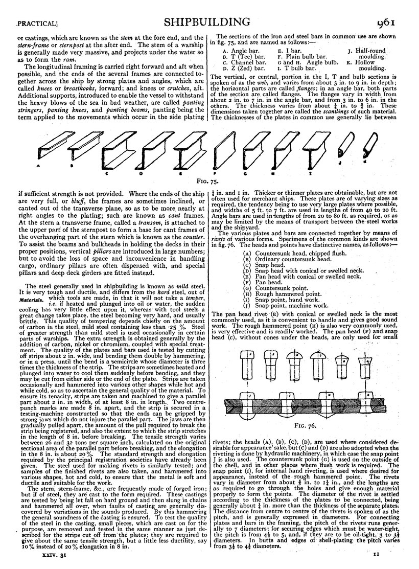
The longitudinal framing is carried right forward and aft when possible, and the ends of the several frames are connected together across the ship by strong plates and angles, which are called knees or breasthooks, forward; and knees or crutches, aft. Additional supports, introduced to enable the vessel to withstand the heavy blows of the sea in bad weather, are called panting stringers, panting knees, and panting beams, panting being the term applied to the movements which occur in the side plating if sufficient strength is not provided. Where the ends of the ship are very full, or bluff, the frames are sometimes inclined, or canted out of the transverse plane, so as to be more nearly at right angles to the plating; such are known as cant frames. At the stern a transverse frame, called a transom, is attached to the upper part of the stern post to form a base for cant frames of the overhanging part of the stern which is known as the counter. To assist the beams and bulkheads in holding the decks in their proper positions, vertical pillars are introduced in large numbers; but to avoid the loss of space and inconvenience in handling cargo, ordinary pillars are often dispensed with, and special pillars and deep deck girders are fitted instead.
The steel generally used in shipbuilding is known as mild steel. It is very tough and ductile, and differs from the hard steel, out of which tools are made, in that it will not take a temper, i.e. if heated and plunged into oil or water, the sudden cooling has very little effect upon it, whereas with tool steels a great change takes place, the steel becoming very hard, and usually brittle. This quality of tempering depends chiefly on the amount of carbon in the steel, mild steel containing less than .25 %. Steel of greater strength than mild steel is used occasionally in certain parts of warships. The extra strength is obtained generally by the addition of carbon, nickel or chromium, coupled with special treatment. The quality of the plates and bars used is tested by cutting off strips about 2 in. wide, and bending them double by hammering, or in a press, until the bend is a semicircle whose diameter is three times the thickness of the strip. The stri s are sometimes heated and plunged into water to cool them suddenly before bending, and they may be cut from either side or the end of the plate. Strips are taken occasionally and hammered into various other shapes while hot and while cold, so as to ascertain the general quality of the material. To ensure its tenacity, strips are taken and machined to give a parallel part about 2 in. in width, of at least 8 in. in length. Two centre punch marks are made 8 in. apart, and the strip is secured in a testing-machine constructed so that the ends can be gripped by strong jaws which do not injure the parallel part. The jaws are then gradually pulled apart, the amount of the pull required to break the strip being registered, and also the extent to which the strip stretches in the length of 8 in. before breaking. The tensile strength varies between 26 and 32 tons per square inch, calculated on the original sectional area of the parallel part before breaking, and the elongation in the 8 in. is about 20%. The standard stren th and elongation required by the principal registration societies have already been given. The steel used for making rivets is similarly tested; and samples of the finished rivets are also taken, and hammered into various shapes, hot and cold, to ensure that the metal is soft and ductile and suitable for the work.
The stem, stern-frame, &c., are frequently made of forged iron; but if of steel, they are cast to the form required. These castings are tested by being let fall on hard ground and then slung in chains and hammered all over, when faults of casting are generally discovered by variations in the sounds produced. By this hammering the general soundness of the casting is ensured. To test the quality of the steel in the casting, small pieces, which are cast on for the purpose, are removed and tested in the same manner as just described for the strips cut off from the plates; they are required to give about the same tensile strength, but a little less ductility, say 10% instead of 20% elongation in 8 in.
The sections of the iron and steel bars in common use are shown in fig. 75, and are named as follows:—
| A. Angle bar. | E. I bar. | J. Half-round |
| B. T (Tee) bar. | F. Plain bulb bar. | moulding. |
| C. Channel bar. | G and H. Angle bulb. | K. Hollow moulding. |
| D. Z (Zed) bar. | I. T bulb bar. |
The vertical, or central, portion in the I, T and bulb sections is spoken of as the web, and varies from about 3 in. to 9 in. in depth; the horizontal parts are called flanges; in an angle bar, both parts of the section are called flanges. The flanges vary in width from about 2 in. to 7 in. in the angle bar, and from 3 in. to 6 in. in the others. The thickness varies from about 14 in. to 34 in. These dimensions taken to ether are called the scantlings of such material. The thicknesses of tie plates in common use generally lie between 14in. and 1 in. Thicker or thinner plates are obtainable, but are not often used for merchant ships. These plates are of varying sizes as required, the tendency being to use very large plates where possible, and widths of 5 ft. to 7 ft. are used in lengths of from 40 to 20 ft. Angle bars are used in lengths of from 20 to 80 ft. as required, or as ma be limited by the means of transport between the steel works and the shipyard.
The various plates and bars are connected together by means of rivets of various forms. Specimens of the common kinds are shown in fig. 76. The heads and points have distinctive names, as follows:—
(A) Countersunk head, chipped flush.
(B) Ordinary countersunk head.
(C) Snap head.
(D) Snap head with conical or swelled neck.
(E) Pan head with conical or swelled neck.
(F) Pan head.
(G) Countersunk point.
(H) Rough hammered point.
(I) Snap point, hand work.
(J) Snap point, machine work.
| Fig. 76. |
The pan head rivet (E) with conical or swelled neck is the most commonly used, as it is convenient to handle and gives good sound work. The rough hammered point (H) is also very commonly used, is very effective and is readily worked. The pan head (F) and snap head (C), without cones under the heads, are only used for small rivets; the heads (A), (B), (C), (D), are used where considered desirable for appearance’ sake, but (C) and (D) are also ado ted when the riveting is done by hydraulic machinery, in which case the snap point J is also used. The countersunk point G is used on the outside of the shell, and in other places where flush work is required. The snap point (I), for internal hand riveting, is used where desired for appearance, instead of the rough hammered point., The rivets vary in diameter from about 58 in. to 114 in., and the lengths are as required to go through the holes and give enough material properly to form the points. The diameter of the rivet is settled according to the thickness of the plates to be connected, being generally about 14 in. more than the thickness of the separate plates.
The distance from centre to centre of the rivets is spoken of as the pitch; and is generally expressed in diameters. or connecting plates and bars in the framing, the pitch of the rivets runs generally to 7 diameters; for securing edges which must be water-tight, the pitch is from 412 to 5, and, if they are to be oil-tight, 3 to 312 diameters. In butts and edges of shell-plating 'the pitch varies from 312 to 412 diameters.
In some positions rivets like the above cannot be driven into place and properly hammered up; resort is then made to rivets which have screwed points, called tap rivets, shaped as shown in fig. 77. That shown at (B) is used where it is necessary to make the surface flush, but not necessary to remove the rivet for examination of plating; and when hove right up, the square head is chipped off and the surface hammered smooth. In other positions patterns (A) or (C) are used as may be most suitable.
An image should appear at this position in the text. If you are able to provide it, see Wikisource:Image guidelines and Help:Adding images for guidance. |
The machines used in the shipyard have been much improved of recent years. The one most used is the punching and shearing machine, on one side of which plates of all thicknesses up to 2 in. may be cut or sheared to, any desired form, while on the other side rivet holes may be punched of any required size. Special shears are provided with V-shaped cutters for shearing angle bars, but in some cases the cutters of ordinary shears Machine tools. may be replaced by V-shaped cutters for this purpose. When the plates and bars leave the shearing and punching machine their edges are rough and slightly distorted, to remove which it is necessary in many cases to plane them; This is usually done by special machines provided for the purpose. In the most modern types theicutters are duplicated and -the machine arranged to cut both ways. When it is required to cut a square edge on the flange of an angle bar to facilitate caulking, a pneumatic chipping machine of recent introduction is frequently used, but this is more usually done in a planing machine. In shipbuilding a great deal of drilling must be done by hand, but, where it is possible, drilling machines are employed. The most modern forms can drill a number of holes at the same time. For countersunk work it is necessary to make the hole funnel-shaped, as will be seen from fig. 77. This shape is rapidly given to the holes already punched or drilled by means of a special drilling machine, which can be very easily and rapidly manipulated. The use of portable drills, to avoid hand labour, is rapidly increasing, and several types are in use, operated by electric motors, compressed air or flexible shafting. They are carried to any position required. The hole made by a drill is cylindrical, but that made in the process of punching is conical. On one side of the plate its diameter is determined by the diameter of the punch, and on the other by the diameter of the die, which must be greater than that of the punch. This taper tends to produce close and sound riveting, as the joint is closed both by the knocking down of the rivet and by the contraction of the rivet on cooling. On the other hand, the operation of punching injures the steel in the neighbourhood of the hole, and for work subjected to great stress this deteriorated material must be removed by countersinking or by drilling the hole to a larger size, or the quality of the material may be partially restored by annealing. The process of annealing consists in heating the steel to a good red, then allowing it to cool very slowly; during this process parts of the material which have been unduly distressed in working regain their strength by.molecular rearrangements in the distressed parts. This process occurs to some extent when hot rivets are introduced into the holes and hammered up. The steel immediately adjacent to the rivet is heated, and afterwards cools gradually as the heat becomes distributed into the body of the plate. In some experiments carried out by the Admiralty in Pembroke Dockyard in 1905, it was found that the effect of punching holes close together, as for a butt-strap, was to diminish the tensile strength of the plates about 10%; that hot riveting restored about half of this; and that when holes were drilled and countersunk right through, also when holes were punched 34 in. and countersunk right through, so as to enlarge hole to 78 in. in diameter, there was no loss.
In addition to the machines mentioned above, many special appliances have recently been introduced into shipyards for the purpose of economically carrying out definite operations rendered possible by the use of mild steel. Ships .built with a bar keel require the garboard strake plates on each side to be flanged on one edge, so as to fit against the bar keel. This flanging was formerly carried out by heating the lates and treating them hot, but now a very powerful machine, called) a keel-plate bending machine, and usually worked by hydraulic power, is employed for the purpose with the plate cold. Flanging plates cold has also become general for a variety of, purposes. In a bulkhead, stiffening is necessary, and for this purpose angle bars, were commonly used; the horizontal stiffeners are now frequently formed by flanging the lower edges of the plates. Instead of fitting an angle bar to connect two plates at right angles to one another, the edge or end of one may be Banged, and half the weight of the angle bapand the rivet work saved. For all such work somewhat lighter Hanging machines than the keel-plate bending machine are used; they are generally worked by hydraulic power, but there is no difficulty in driving them by any other means.
Another modern appliance is the scarfing machine, which is used chiefly in connexion with the lapped butts of shell and other plating. Before its introduction it was usual to bring the ends of the plates together and cover the joint with a short plate called a butt-strap, secured to both plates with a proper arrangement of rivets (see fig. 78). It is now more usual in merchant ships to work overlap butts, some half of the weight of the butt-strap and riveting and other work being saved thereby, although the appearance may not be quite so sightly. The difficulty with this system is that the passing plates on each side have their edges lapped over the ends of the lap-butt, and in order that they may be brought close some machining is necessary; this is called scarfing, i.e. slotting away the corner of the projecting butt so as to produce smooth su aces for the side laps (see section at A B, fig. 78). The machine used for this operation is a slotting machine with two heads, so as to slot both edges of the plate at the same time; it is provided with a table which can be adjusted to the necessary bevel, so that the slotting tools may reduce the thickness of the edges operated on in a gradual taper to a knife edge. A more recent appliance for reducing weight is the joggling machine. As already described, the usual method of working the shell-plating is by alternate inside and outside strakes of plating, the outside plates overlapping the inside plates, and the space between them and the frames being filled in by slips or liners. These liners throughout the ship amount to a considerable weight, and the object of the joggling is to do away with the necessity for them. This is effected by shaping the outside plates as shown in section b. fig. 79. Sometimes the frames are joggled instead of the plates, as shown in section c, fig; 79; the inside plate lies in the recessed portion of the frame formed by the joggling process, and the outside plate on the unrecessed portion, its edge lapping over the edge of the inside plate the usual width. The angle bar in this case must be heated, and the hydraulic press is placed so as to be readily accessible for the handling of the part to be heated. The system of joggling the frames has not been adopted to nearly so large an extent as that of joggling the plates.
Frame-bevelling machines appear to be growing in favour. "The machine is placed on rails, near to and across the mouth of the frame furnace, so that it can be readily placed in position for the frame bar to be drawn out of the furnace directly through it, and moved to one side when not required. In the machine a series of rollers, which can be inclined to suit the varying bevel required, operate on the bar. The inclination of the roller is varied as the bar passes along, a dial and pointer giving the angle of bevel at each instant. As the bar passes through, the workman, with his eye on the dial, manipulates the machine so as to give it the required bevel. It is, afterwards completed on the slabs, the form being taken from the scrive-board in the usual way.
The shipyard should be supplied with modern machinery of the most approved type, in order to produce the best work at economical rates: rolls for straighten in, rand bending plates, for fairin and bending beams and angle bars; shaping and slotting machines; lathes and milling machines; heavy planing machines. It should also have a blacksmith's shop, saw-mills, joiners' shops, &c., all fully equipped for completing, as far as possible, the work of the yard. The workshops and machines should be distributed so that, as far as possible, the material moves steadily along, as the various operations are performed upon it, to its place in the ship. Pneumatic tools are often preferred for light work, such as chipping, drilling, rimering and caulking; they are also occasionally used) for riveting, but they are not yet much in favour for this class of work. Hydraulic power is particularly well adapted for heavy presses, such as for keel-plate flanging, for punching and shearing, and especially for punching manholes and lightening holes in plates, and for heavy riveting. It is also very successfully applied for pressing to shape a great variety of small fittings made of steel or iron. For such machines as rolls, ordinary shears and punches, winches, &c., separate steam engines are still frequently fitted, but there is a very marked tendency to replace all these by electric motors. Electric power for driving all the machinery has been introduced into many shipyards. It has many advantages: all the power required in the yard may be generated in one building in any position, containing the boilers, steam engines and electric generators, and the, whole may be designed and worked so as to secure great economy. The current is supplied either to motors directly driving the heavier or outlying machines, or to motors driving a line of shafting where the machines are of a lighter character and are arranged in compact groups. Fixed machines can be placed where most convenient for the work, without any reference to the position of the boilers or.other machinery, and a large number of machines can be very readily made portable for the lighter classes of work, The power may be transmitted with but little loss, whereas with steam-driven machines at a distance from the boilers, lines of steam piping must be introduced, and loss of power is entailed. The savin which the system of electric driving effects over that of steam driving in the consumption of coal in a large shipyard is considerable, an disclaimed by those who have adopted it to be sufficient to justify the large capital expenditure required to convert; a shipyard from the latter system to the former.
As the plates, beams, angle bars, Z-bars, &c., are delivered, they must be stored in convenient racks, with marks showing for what purpose they are intended, so that they can be readily identified and removed without loss of time. When required, they are taken from the racks, and the edges, butts and rivet holes carefully
An image should appear at this position in the text. If you are able to provide it, see Wikisource:Image guidelines and Help:Adding images for guidance. |
marked upon them before they are taken to the machines where the shearing, punching, drilling, shaping, &c., are carried out, after they are taken to their proper position in the ship.
Cranes. In many shipyards great attention has been given to the questions of the economical handling of the cranes material, and very costly and novel appliances, are to be found in these yards for the pur- pose. As an example mention may be made of the overhead cranes fitted at the Union Ironworks of San Fransisco. A framework of wood is built up over the entire building berth, the structure being well braced in all directions for carrying two travelling girder cranes. There are four building berths fitted in this manner, and the latest has a length of 408ft., a clear breadth of 80 ft., and clear height of 72ft. A swing crane of 50 ft. spread at each end of the erection increases its effective length to 500 ft. Each of the travelling girders carries a trolley, with motion tranvese to the ship; five tons can be so lifted, and parts of the ship's struc- ture not exceeding this weight can be taken from the ground anywhere in the neighbourhood of the structure and conveyed to any desired spot in the ship. The driving power is electric. The longitudinal travel of the girders is 180 ft. per minute the transverse travel of the trolley and speed of lift, each 90 ft. per minute. A manila rope is used for hoisting, except for plates under the bottom and counter, where a wire rope is used.
At Newport News, in Virginia, the structures are differently arranged, being on the cantilever travelling-crane principle. There are five such structures in the yard; three of them are wood the
An image should appear at this position in the text. If you are able to provide it, see Wikisource:Image guidelines and Help:Adding images for guidance. |
last two of steel. The largest is 700 ft. long. One trestle structure or gantry, serves two building berths, and runs longitudinally between the two. On the gantry is mounted a double cantilever crane, having an effective reach of 95 ft. on each side of the centre; this outreach is sufficient for a ship 70 ft. broad on each side of the trestle. The height of the cantilever above the ground is some 90 ft., the load that can be raised is 15 tons, and if necessary a bulkhead up to that weight can be lifted bodily into place. The speed of lift for this weight is 100 ft. per minute, and for lighter loads 700 ft. per minute. The speed of the trolley along the cantilever is 400 to 800ft. per minute, and of the whole crane longitudinally is 400 to 700 ft. per minute. All movements are made by electric power. Similar gantries and arrangements are used in other American shipyards. The view shown in fig. 80 (Plate VIII.) represents one of these structures as fitted in Messrs Cramp’s shipyard in Philadelphia. At the yard of Messrs C. S. Swan & Hunter, on the Tyne, similar structures have been erected since 1894; besides carrying cranes, these have standards and Stiffening girders, from which ships under construction are shored for fairing. Roofs and sides are fitted to protect the ship, and the workmen engaged in building her, from the weather. The side supports are three in number, and serve for two berths; they are formed of steel lattice-work, with standards mostly 20 ft. apart. The clear height of roof is 83 ft., and clear breadth of berths 68 ft. and 73 ft.; a roadway on the ground level is left free on each side of the berths inside the standards. Two revolving 3-ton electric cranes travel along paths suspended from each roof; their jibs have sufficient radius to lift material from the roadways and deposit it at the centre of the ships building. The longitudinal speed of these cranes is 300 ft. per minute; speed of lift, 100 ft. per minute. A third berth is served by a travelling cantilever crane on top of the adjoining roof. At Messrs Harland & Wolff’s yard at Belfast another modification was introduced in 1897 (see fig. 81, Plate VIII.). In this case the structure takes the form of a travelling gantry or bridge over the building berth, the legs running on rails at, the ground level. The gantry, which is driven by hydraulic power, has three traversing cranes and four 4-ton swing cranes. It was designed to facilitate the lifting of plates and portions of the structure into position, and also to support the hydraulic riveting machines and other appliances for the carrying out of the work. The success of the appliances, first used in the “Oceanic,” has led to a further extension for other ships in hand.
Course of Construction
The first steps taken on the receipt at the shipyard of the design drawings and specifications, which have been generally described on page 957, have for their object the provision of detailed drawings of the structural arrangements, which will enable materials for the various parts to be ordered from the manufacturers, and of information for the guidance of the workmen in erecting the structure.
A wooden model of half of the exterior surface of the ship, called the “half-block” model, is immediately prepared from the sheer drawing, generally to a scale of 14 in. to the foot for a large ship and a somewhat larger Scale for a small one, and on its surface are carefully drawn the main frames, the edges and butts of the outer bottom or shell-plating, together with the positions of decks, longitudinal and other features which influence the detailed arrangement of the framing and shell plating, the particulars of which are fixed by the specification and the midship and other sections. The work on this model is carried out concurrently with the laying off of the ship, which will be described presently, so as to be complete by the time the latter is sufficiently far advanced to enable full-sized measurements of the breadth of the plates to be obtained. The lengths of the plates are then measured from the model and the breadths from the mould loft floor, a small surplus on the net measurements being allowed to provide for inaccuracies; and the whole of the Outer bottom plating ordered from the manufacturers. The whole of the framing is also ordered, the lengths of the various parts being measured from the model.
A similar block model is made to the shape of the inner bottom, if one is to be provided, or of the top of the ballast tanks, as the case may be; and in a battle-ship a block model will be made of the protective deck if it should have much curvature or sloping Sides. All details of plating, framing, beams, carlings, hatchways, &c., will be shown on these models, and the dimensions of all the parts will be carefully measured off and the material ordered of the manufacturers; the breadths of the plating being obtained as in the case of the outside bottom plating.
For flat or nearly flat surfaces such as flat keel plates, vertical keel, bulkheads, decks, engine and boiler bearers, &c., the detailed arrangements of plating and frames are made on drawings, from which the dimensions are taken for ordering the material from the manufacturers; while the drawings themselves constitute working drawings which are issued for general guidance in building the ship.
Drawings of details of important structural castings or forgings, such as the stem, stern post and shaft brackets, are also among the earliest taken in hand, but the patterns to which these parts are made, when they are large and complicated castings as in a warship, cannot generally be completed without information obtained from the mould loft floor.
Laying off is the name given to the process of drawing the lines of a ship to full size in plan and elevation in order to determine the exact dimensions of the most important and fundamental parts of the structure. The necessity for drawing to full size arises from the extreme accuracy with which the dimensions of the various parts must correspond with one Laying off. another in order that when assembled there may be no irregularity or unfairness in the surface of the ship; the methods of ordinary mechanical drawing to a small scale being inadequate for this purpose, on account of the analytically indeterminate nature of the curves which define the form of the ship. The process is carried out on a specially planed and blackened floor, most conveniently of rectangular shape, and of such a size as to take in the full depth of the ship in its width. The building or room in which the floor is situated is called the “mould loft,” and is an important adjunct to the shipyard drawing office.
The rationale of the methods of projection of points and lines and rabatment of planes used in laying off is subjected to a detailed examination m the article Geometry, part III., Descriptive, vol. xi., and therefore will not be referred to in this article, which is confined to a description of some of the detailed problems which occur in actual practice, the solutions being often approximations which are found sufficiently exact for practical purposes. In different localities and in the construction of different types of vessel, the extent to which the process of laying off to full size is employed varies considerably. In some yards laying off on a large scale on paper is relied on almost entirely, and very little full-sized work on the floor is considered necessary. This chiefly applies to ships of stereotyped form, such as ordinary “tramp” Steamers, the lines of which have very little curvature for the greater part of their length. In the American Lake shipyards for the cargo vessels employed on the Great Lakes templates are very carefully and ingeniously made for the framing, one set sufficing to mark off all the frames on the greater portion of the ship’s length. In a similar way one template is made for each strake of plating and used to mark off the whole of the plates of that strake, a slip mould being used when they begin to depart from the parallel midship body. The types of vessels in which the greatest complication of structure occurs and in which the highest degree of accuracy in building is necessary are passenger ships and war vessels; the description of the process of laying off, which follows, while generally applicable to alltypes of vessels, refers more particularly to the practice followed in building war vessels at the British Government Dockyards and at the more important shipbuilding centres in the United Kingdom.
The nature of the Sheer Drawing, with a description of the principal lines shown on it, has been stated on p. 957. Specimen sheer drawings of different types of ships are shown on Plate IX. Fig. 83, Plate IX., is a sheer drawing of the Midland Railway steamer “Londonderry,” designed by Professor J. H. Biles, LL.D., of length between perpendiculars Sheer drawing. 330 ft., breadth moulded 42 ft., depth 25 ft. 6 in., displacement 2200 tons, speed 21·7 knots. Fig. 82, Plate IX., is the sheer drawing of the battleship “Lord Nelson,” whose dimensions and other articular are set forth in the article on Ship, page 898. Her form over the midship portion below the waterline and above the turn of the bilge is flattened so as to enable her to be docked in a dock existing at Chatham when she was built, and at the same time to secure the greatest possible beam of ship at the water-line; and the bottom of the ship out to the dotted line in the half-breadth plan is absolutely flat so as to enable her to be docked on two or more lines of blocks whose upper surfaces lie in one plane, thereby reducing the docking strains, a system adopted for the first time in the “Lord Nelson” and in all succeeding vessels of large size in the British Navy since this vessel. In Plate IX. figs. 85 and 87, the half-breadth and body plans of the royal yacht “Alexandra” are given in association with the profile, fig. 84, in place of the usual outline sheer, which is omitted to save space. In each of these sheer drawings the names of the various lines have been added; whereas in ordinary practice only the numbers of the stations in the sheer and half-breadth and of the sections in the body are given. In the sheer drawing, fig. 83, very little more is given in the three plans than the various sections and the traces of the planes, whose intersections with the surface of the ship they are; in such a case the sheer drawing is generally spoken of
as the lines, and is only used for giving the outside form of the ship, 
(Upload an image to replace this placeholder.)
other information required for laying the vessel off and making the necessary moulds being usually given on other drawings. The sheer drawing of the “Lord Nelson” contains the information usually given concerning the form of the ship and other features of the design required for laying the vessel off, ordering the material for her construction and afterwards erecting the same in position. In these drawings it has been necessary for the sake of clearness to reduce the number of square stations and water or level lines commonly shown in drawings of this character. The number of these lines is fixed in the preparation of the design by the necessity of accurately defining the surface of the ship so that the intentions of the designer as regards form, displacement, and what may be called the geometrical features of the ship may be realised. In a large warship there are usually 21 square stations shown, including the forward and after perpendiculars, the distance between which defines the nominal length of the ship. The water-lines are 3 to 4 ft. apart. Intermediate square stations and water-lines are frequently introduced where the curvature of the surface of the ship is rapidly altering; as at the ends and below the bilge. It is usual, and obviously sufficient in the sheer drawing as well as in the process of laying off, to show only one-half of the ship on one side of the longitudinal vertical plane of symmetry. Thus, in the half-breadth plan only the port side of the ship is drawn; and in the body plan, for greater clearness, the half ship is further divided, the part forward of the midship section, or square station at the middle of the length of the ship, being shown on the right of the middle line of that plan, pnd the part aft of the midship section on the left of the middle ine.
Other Drawings.—The profile and plans and the midship section have also been described in this article. The profile and plans of H.M. yacht “Alexandra” are given on plates. Fig. 84, Plate X., is the profile which shows in sectional elevation all the decks, bulkheads, machinery, living spaces, store spaces, &c.; figs. 86, 93, 94, 95 and 96, Plate X., give the plans of the promenade deck, upper deck, main deck, lower deck and hold respectively with important fittings shown upon them; figs. 88, 89, 90, 91 and 92, Plate X., give sections of the ship showing the inboard works at stations E, D, C, B and A on the profile respectively; and on fig. 97, Plate XII., is given the midship section with all the principal scantlings of the framing and plating. Fig. 98, Plate XIII., also gives the midship section of H.M. battleship “Lord Nelson.”
Any two of the three plans of the sheer drawing may be taken to represent the “horizontal” and “vertical” planes of Descriptive Geometry, and are theoretically sufficient to define the shape of the vessel completely, but the three plans are practically necessary for the sake of clearness and are always used.
In the design sheer drawing the lines may represent the intersections of planes with the surface of the framing of the ship, or with an imaginary surface having a mean position between the irregularities of the surface of the ship caused by the system of plating adopted. The former system is the more usual in the drawings of steel-built merchant ships, necessitating an allowance on all measured dimensions used in calculating displacement, &c.; the latter system is usual in warships, in which the surface represented by the sheer drawing of a ship plated with raised and sunken plates strakes as described on p. 962, would be an imaginary surface midway between the outsides of the raised and the sunken strakes. A sheer drawing on this latter system is said to show displacement lines in contradistinction to the former system which shows “moulded” or frame lines. In the case of vessels with a plank sheathing over the bottom the surface shown on the sheer drawing is the outside of the planking.
As the primary object of the laying off of the ship is to ascertain the shape of the frames, the surface of the outside of the frames is always that which is laid off on the mould loft floor. If displacement lines are given in the sheer drawing a preliminary process of deriving from them the moulded lines is necessary before laying off on the floor. The process, to be strictly accurate, involves setting in the requisite distance along the normal to the surface shown in the sheer drawing. This is easily done at the midship section, where the normal to the surface lies in the plane of the section and coincides with the normal to the curve of the square station in the body plan, or at the practically vertical parts of the sides of the ship, where the normal to the surface lies in the water plane and coincides with the normal to the waterline in the half-breadth plan. In other positions, however, it would be necessary to rabat a plane containing the normal on one of the planes of reference, set in the required distance along the rabatted normal, find the projections of the point in the frame surface so obtained and of other similar points, and thus obtain the projections of curves on the frame surface, which by their intersections with orrlinates and water-lines would give a new set of square stations and water-lines corresponding to the moulded surface of the ship. Such a process, though simple, is more laborious than is necessary in view of the degree of accuracy required, and in practice it is customary to set in normal to each square station a distance slightly greater than the thickness of the plank and plating, the increased distance required being roughly estimated from a consideration of the obliquity of the water-lines, without producing any sensible error.
The frame lines having been obtained, it is customary at some shipyards to “fair” the body on paper on a larger scale than that of the sheer drawing, before laying off on the floor. This saves a certain amount of labour in fairing the full-sized body on the floor, the errors in the body as first copied on the floor, which it is the object of the fairing process to correct, being Fairing the body. proportional to the increase in scale in first copying. The process is similar to the full-sized fairing which is described below.
A straight line is drawn on the floor parallel to a fixed straight batten nailed to the floor a short distance from the wall of the building to represent the load water-line in the sheer and body plans and in such a position that the whole depth of the ship can be drawn with regard to it within the limits on the floor and clear of the batten, the inner edge of which becomes the base-line of the sheer, half-breadth and bod plans. The fore and after perpendiculars of the sheer and half-breadth plans are drawn at right angles to this line and the fixed batten in convenient positions near the ends of the floor, the fore perpendicular on the right and the after perpendicular on the left as in the sheer drawing, and so as to allow the extreme outlines of the stem and stern to be drawn upon the floor together with not less than one-fifth of the length of the sheer and half-breadth plans at each end of the ship. A line perpendicular to the water-line and the fixed batten is drawn, usually near the middle of the floor, to represent the middle line of the body plan. The middle line of the half-breadth plan is usually taken as coinciding with the base-line, the inner edge of the fixed batten. The level or water lines shown on the sheer drawing are drawn in on the floor parallel to the load water-line so as to serve for both the sheer and body plans. Ordinates representing those given in the sheer drawing, which correspond to the sections in the body plan, are drawn in the sheer and half-breadth plans and others are added where desired, so also are additional water-lines between those shown on the sheer drawing and above the load water-line, so that in full-sized drawing on the floor the sections and stations may be sufficiently near for fairing the whole of the external form of the ship. If, as is usually the case, the ship is too long to be laid off in one length on the floor the midship portions of the sheer and half breadth plans are drawn superposed over the forward and after parts, and are usually contracted longitudinally as will be described presently.
The distances from the middle line along each water-line in the body plan of the original sheer drawing, or of the enlarged body when the process of preliminary fairing has been adopted, to the intersection of the water-line with each section are measured to scale and tabulated. At the lower parts of the body, in the vicinity of and below the “bilge,” where the water-linescut the square stations very obliquely and the points of intersection become somewhat indeterminate, diagonal lines as shown by 1D, 2D in fig. 99 are drawn in the sheer drawing in such positions as to intersect as many as possible of the square stations approximately at right angles, and the corresponding diagonal lines are drawn on the floor. The distances from the middle line of the body plan in the sheer drawing along the diagonal lines to their intersections with the sections are measured and tabulated. It is usually desirable, especially in ships with a great extent of practically flat bottom, to draw bow and buttock lines to include this portion of the surface, such as IB in the figure, as the diagonals approach more or less closely to bow and buttock lines and shorter measurements are required in transferring the lines; the heights of their intersections with the transverse sections above the base-line being measured and tabulated. The draught of water of the ship at the forward and after perpendiculars is given in the specification enabling the underside of keel in the sheer plan to be drawn in on the floor between the points where the rise of keel commences at the extremities. The flat part of the keel is generally uniform in width for the greater part of the length of the ship, and tapered at the extremities. The line representing its side must be drawn on the floor in the half-breadth plan. The height of keel-line above the base-line at each station in the sheer plan and the corresponding half siding of keel are the co-ordinates of the lower extremity of the corresponding transverse section in the body plan. The lower extremities of the-sections are at once fixed in the body plan by the intersections of their horizontal and vertical Ordinates transferred from the half-breadth and sheer plans. For the upper endings of the transverse sections in the body plan a level line is generally drawn on the body of the sheer drawing just above the projection of the upper deck edge and the sections at the square stations produced to meet it. The intersections of this water-line with the sections are measured and tabulated.
The whole of this process of measurement and tabulation is frequently done in the drawing office, and the “loftsman” or person who conducts the laying off on the floor is not supplied with the sheer drawing, but only with these tables of “offsets,” and similar tables for the lines in the sheer and half-breadth. The process, however, is the same in either case.
The tabulated measurements for the sections of the body plan are then set off full size by means of long measuring staffs on the lines on the floor, corresponding to those in the sheer drawing on which the measurements were taken, and thus give points whose coordinates are to those of the corresponding points in the drawing in the ratio of 48:1; if the drawing from which they were taken was to a scale of 14 inch to the foot as is usually the case. A suitable wood batten is then bent or “penned” as nearly as possible through the series of points on the several water, diagonal and buttock or bow lines corresponding to each square station, being held in position by nails, specially adapted for the purpose, lightly driven into the floor, the batten in each case being adjusted so as to lie in a fair curve. Usually the batten will not under these conditions pass through all the points found for the curve on account of irregularities introduced or magnified in the process of enlarging to full size, and it must be allowed to take up a mean position passing outside some of the points and inside others. All of the sections in the body plan are drawn in with chalk in this way. The section where the greatest breadth of the ship occurs, usually at or near the middle of the length, must have the line parallel to and half the moulded breadth of the ship from the middle line for a tangent, and no section must project beyond this line.
The intersections of each section thus drawn, with the water and other lines, are the vertical projections on the body plan of points, the horizontal projections of which lie in the horizontal trace of the transverse plane at the corresponding square station or ordinate in the sheer and half-breadth plans, and are at the same perpendicular distances from the middle line of the half-breadth as the corresponding vertical (projections are from the middle line of the body. For example, in fig. 99 p1 and q1 are the projections in the half-breadth of the same points of which p and q are projections in the body plan, and are found by making the ordinates of p1 and q1 measured from the middle line of the half-breadth plan at square station 2 equal to the perpendicular distances of p and q respectively from the middle line of the body plan. Thus points in the projections in the half breadth of the water and diagonal lines can be found from the body plan already drawn, and in order that the surface of the ship may be fair, the series of points corresponding to any water or diagonal line must lie on a fair curve. In the case of a diagonal line the distance from the middle line of the body to the intersections of the diagonal with the square stations may be measured along the diagonal, and set off on the corresponding square stations in the half-breadth. This gives the true or rabatted form of the intersection of the diagonal plane with the ship's surface, and this, equally with the projected diagonal, must be a fair curve if the surface is fair. The diagonals are also projected into the sheer plan by measuring the height above the base-line at which each diagonal in the body plan cuts each square station, and setting up this height from the base-line of the sheer plan at the corresponding square station. The projections of the bow and buttock lines in the sheer plan are obtained in a similar manner. Thus in fig. 99 V2 is projection in the sheer plan of the intersection of the bow plane 1B with square station 2, and t2 is the projection in the sheer of the intersection of water-line 2WL with the same bow plane. The water-lines and diagonals in the half-breadth and the diagonals and bow and buttock lines in the sheer may thus be drawn as fair lines by the help of battens. and if the lines do not pass through all the points obtained by projection from the body plan, the sections in the latter are rubbed out and new ones obtained from the lines in the half-breadth. This process should be repeated until the curves in both plans are fair and the intersections correspond accurately with one another as the projections of points in space.
An image should appear at this position in the text. If you are able to provide it, see Wikisource:Image guidelines and Help:Adding images for guidance. |
- Fig. 99.
No frame of the ship, however, is made to the curves of these water
and diagonal lines, so that their true shapes are not required for any
practical purpose except fairing the body. For the whole
length of the ship, except about three to four twentieths at
each end, space and labour are therefore saved and greater
accuracy is ensured by using the contracted method of
Contracted method
of fairing.
fairing. In this method the ordinates of the half-breadth are set only
from 15th to 110th of their true distance apart, while the transverse
measurements are made to full size as before, thus making the curvature
of the water and diagonal lines sharper throughout the region
over which it would otherwise be somewhat flat and indefinite. As
the curvature of the contracted level and diagonal lines depends upon
the differences between the lengths of the ordinates of the curves and
not upon their actual length, a further saving of space is effected by
measuring the distances to be set up as ordinates in the half-breadth
not from the middle line of the body but from a point selected
arbitrarily in each water or diagonal line, generally a few inches
outside the midship section. By suitably varying the distances
outside the midship section of these arbitrarily chosen points in the
different water and diagonal lines, it can be arranged that the curves
in the half-breadth do not interfere with one another, an advantage
from the point of view of clearness. With the above modifications
the process of fairing by the contracted method is precisely similar to
that when the ordinates are their full distance apart.
In fig. 88 the diagonals 1D and 2D are shown laid off by the contracted method, the spacing of the ordinates in the contracted half-breadth being, 16th of that representing the spacing in the diagram of the uncontracted sheer and half-breadth. In the contracted half-breadth the ordinates 4r1, 5s1. &c., are equal to the distances Or, Os, &c., measured to sections 4, 5, &c., in the body, O being a point arbitrarily selected in the diagonal 1D.
The principle of contracted fairing is sometimes extended by the 
(Upload an image to replace this placeholder.)
provision of a large drawing-board 4 or 5 ft. broad and long enough to take the whole length of the ship on a scale of 124th full size. The ordinates of the half-breadth and sheer being set off on the board to this scale, any line in which the difference between the greatest and least ordinates does not exceed the breadth of the board can be faired thereon by this contracted method. This allows considerable lengths of the midship parts of diagonals and water-lines, and such lines as decks at middle and side, and any other lines of very flat curvature, to be faired on the board, resulting in a great saving of time and labour, owing to the convenient height at which the board can be placed, and to greater accuracy, as the fairness of the lines can be better seen and judged.
At the forward and after ends of the ship the correct shapes of the water-lines are required in order to determine the shapes of the stern and stern-post, besides which the curvature of these lines is too great to permit of contraction of the abscissa scale. These parts are, therefore, faired by uncontracted water and other lines as already described, Fairing the ends.except that bow and buttock lines are used to less extent than in the flatter portions of the vessel.
Care must be taken that at the junction of parts of the ship faired by separate processes there shall be a considerable overlap throughout which the water and other lines in the two parts are identical in order to ensure the continuity of the surface.
Fig. 100.
The detailed drawings of the stem and stern castings already referred to must ensure that these castings shall form a fair continuation of the outside surface of the plating or sheathing. They are perhaps most complicated in the case of sheathed armoured warships where the surfaces of “rabbets” or recesses for housing the bottom and armour plating and the wood sheathing must also conform to the lines of the ship laid off on the Hoor. A sketch of the stem casting for an armoured. sheathed ship with a ram bow is given in fig. 100, the sections being shown to a greater scale than the elevations for the sake of clearness, except the section at the water-line AA, which is drawn to illustrate the method of ending the water-lines, similar sections being drawn on the Hoor at the other water-lines. The fore edge of the stem is drawn in full size in the sheer plan on the floor in its correct position relatively to the fore perpendicular and waterlines by measurements taken from the sheer drawing, and the projections of the line of the inner angle of the rabbet for the shell plating, called the “middle of rabbet,” marked h in the figure, are drawn in the sheer and body plans as fair lines. It should be 'observed that in the figure h, the middle of rabbet and b, the fore edge of rabbet of plating are shown in side elevation as coincident lines on account of the smallness of the scale; they will not be generally coincident on a full-sized projection on the Hoor. The middle of rabbet line is best faired in an expansion drawing. In this method a batten is bent to the curve of the-projection of the line in the sheer plan, and the position of the water-lines where sections of the stem have been shown on the drawing are marked on the batten, which is then allowed to spring strai ht along a straight line drawn in any convenient position on the goof, and the positions of the waterlines are transferred from the batten to the Hoor. The distances such as xh in the section at AA are measured from each section given in the drawing and set up in full size perpendicular to the straight line on the floor at the positions corresponding to the sections. A fair line through the ends of these perpendiculars will give the distance xh at any position in the length of the stem and enable the projections of the middle of rabbet-line to be drawn accurately in the body and half-breadth plans.
To end any water-line such as AA in the half-breadth plan a perpendicular to the middle line of the half-breadth is drawn from the intersection of the line AA, with the projection of the middle of rabbet-line in the sheer plan, and the distance xh, taken from the body plan, or direct from the expansion of the middle of rabbet line, is set out from the middle line of the half-breadth; the point h is the ending of the water-line AA required. The waterlines having been drawn and ended in this manner, additional ordinates coinciding with the transverse frames are drawn in the half-breadth plan and their projections obtained and faired in the body plan, in order to define more closely the somewhat twisted surface of the ship in the neighbourhood of the stem. Fairing these frame sections may involve correction and adjustment of the endings of the water-lines, which corrections are made-subject to the condition that the projections and expansion of the middle of rabbet-line must remain fair curves. With the middle of rabbet thus fixed in pro er relation to the faired surface of the fore end of the ship, the sections of the stem by the water-planes can be reconstructed in the half-breadth plan by the help of the drawing of the stem and of any additional information contained in the specification as to the nature of the fastenings of the plank and plating to the casting and the length of the hood ends. Where the general direction of the stem is considerably out of the vertical, sections of the frame surface by planes normal to the fore edge of the stem are obtained by the help of the closely spaced frame sections, and rabatted on the sheer plane; and sections of the stem casting constructed on them as in the case of the water-lines. In this way as many points as are required are obtained in the various lines in the surface of the stem, viz. the after edge of the casting, and the various angles of the rabbets, and these lines are faired so far as they are continuous in the three plans. The shell and protective plating and lank sheathing are also put on outside the various sections of the frame surface for a short distance in the neighbourhood of the stem, and the surface of the stem forward of the fore edge of the rabbet is faired in with the outside surface of the ship.
A plain batten mould is made to the outline of the stem in the sheer plan, and the projections of the lines of rabbets and of gulleting, position and shape of webs for connecting to decks and stringers and to the wood keel, lines of rabbets for connecting to keel plates at the lower end and to the tuck plate at the upper end (if the casting is not continued right up toStem mould. the forecastle deck), the position of the fore perpendicular and load water-line are marked upon it. Sections of the casting taken from the floor are painted on the mould, the centre lines of the sections indicating the position where they are taken, showing more particularly the changes in shape of the casting at such positions as the upper and lower edges of the protective plating and the upper edge of? the plank sheathing. The stem mould thus gives complete information for the preparation of the pattern for the casting. The positions of the fore perpendicular and load water-line marked on the mould are transferred to the casting when made, and enable the stem to be erected in its correct position at the ship.
The after end of the ship is faired and the mouliii for the stern post and other castings prepared in a similar manner. The process of preparing the moulds for the stem and stern post is also generally similar to the above in the case of an unsheathed ship, but the castings are less complicated owing to the absence of the plank sheathing.
The whole of the 21 square stations which constitute the original body plan having been faired as described above, it is usual to calculate the displacement and position of centre of buoyancy of the ship from the lines laid off on the floor to ensure that in the process of fairing no departure of any consequence has been made from the original design.Displacement calculation. For this purpose the steel plating and wood sheathing, if any there be, must be put on by a process the inverse of that described as taking off the plank. If any serious departure from the original design should be discovered as the result of this calculation, the lines must be corrected and again faired.
The transverse frame lines are the intersections with the frame surface of transverse vertical planes passing through the lines of intersection of the two exterior surfaces of the flanges of the frame angle bars, or of the web and flange of any other type of rolled section which may be used for the frame. The distance between two adjacent frame lines, called Frame lines. the “frame space,” is given in the specification, and the positions of the frames relatively to the ordinates are shown in the sheer plan of the sheer drawing. The frame space in a warship is commonly 4 ft. within the limits of the double bottom and 3 ft. forward and aft. In a merchant ship the spacing is usually less. The positions of the planes of the frames are set off along the middle line of the half breadth plan, the proper scale being used in the contracted half breadth, and ordinates are drawn to represent their traces in the half-breadth and sheer plans. The projections of the frame lines in the body are obtained from the intersections of the ordinates with the water and diagonal lines in the half-breadth and the bow and buttock lines in the sheer plan in a manner already described in the case of the more widely spaced stations used in fairing the body. These frame lines in the body should require no further fairing if the work has been accurately done when using the griginal square stations, and they can be at once rased in on the floor.
As already stated, it is usual to dispose the transverse framing of a ship entirely in planes perpendicular to the trace of the load cam water-plane with the longitudinal plane of symmetry frames of the ship. This practice leads to a large and varying bevel being given to the frame bars at the ends of a vessel with a very bluff bow or stern, and it becomes a practical question Cant frames. whether it would not be better at such parts to dispose the frames in planes which are more nearly normal to the general surface of the ship and which need not be perpendicular to either of the three planes of reference. The disposal of frames in this way, more usually in planes perpendicular to the half-breadth planes only, when they are called “cants,” is in common use in wood shipbuilding, it being of great economical importance that the timber frames shall be of square or nearly square section, but it is also adopted in iron and steel ships of unusual form or having special features, such for instance as a lifting screw propeller.

Fig. 101.
To lay off a cant frame or “cant”: Let the traces of the cant be a′b′, ab in fig. 101. Let LL be the projections of a level line in the three plans intersecting ab at b in the half-breadth. Then b, in the sheer is the vertical projection of b, and a curve through all such points as b1 is the projection in the sheer of the shape of the frame or, as it is called, of the moulding edge of the frame. b2 in the body, where a2b2 is equal to the perpendicular distance of b from the middle line of the half-breadth, is a point in the projection in the body plan; and bg where agbs is equal to ab is the position of the point, when the cant plane is hinged about a′b′ until it is parallel with the body plane. Hence a curve drawn through all such points as bg is the true form of the moulding edge of the cant. To obtain the angle which the surface of the ship makes with the plane of the moulding edge, a plane parallel to that of the moulding edge and distant from it the width of the bevelling board must be laid off in a suitable position in the body plan. Let g′c′, gc be the traces of such a plane where af, the normal distance between it and the plane whose traces are a'b', ab, is the breadth of the bevelling board. The vertical projections of c, viz. c1 and c2, in the sheer and body are found in the same way as those of b; but in order to obtain the rabatted curve of the bevelling edge in such a position relatively to the moulding edge that the perpendicular distance between the two curves measures the bevelling in the same way that the perpendicular distance between two frame lines of the square body measures their bevelling, it is necessary to first project the bevelling edge on the plane of the moulding edge before rabatting the latter. The whole operation is effected by making az as in the body equal to fc in the half-breadth, where af is perpendicular to ab and gc. A curve through all such points as c3 is the bevelling edge laid off in the position relative to the moulding edge required, the bevellings being taken in a similar manner to those of the ordinary transverse frames.
Spots on the cant can also be obtained from diagonals as follows:—In fig. 102 let DD be the projections of a diagonal line in the three plans cutting the horizontal traces. of the moulding and bevelling edges at d and e in the half-breadth.
An image should appear at this position in the text. If you are able to provide it, see Wikisource:Image guidelines and Help:Adding images for guidance. |
Fig. 102.
The projections d1, e1 in the sheer and dz, eg in the body of the intersections of the diagonal line with the planes of the moulding and bevelling edges are obtained in the same way as in the case of the level line, and the method of obtaining the rabatted positions, when the plane of the moulding edge, with the bevelling edge projected upon it, is turned about a'b until it is parallel to the body plane, is also analogous; but in this case the corresponding points of the moulding and bevelling edges are in different level planes did, ezei. Points in the rabatted curves of the moulding and bevelling edges of the cant may also be obtained from the intersections with bow and buttock lines, as shown in fig. 103, where BB are the projections of the bow or buttock line in the three plans.
An image should appear at this position in the text. If you are able to provide it, see Wikisource:Image guidelines and Help:Adding images for guidance. |
Fig. 103.
The method is analogous to that described above when using level lines and as shown by the
figure, h3 and k3 being rabatted positions of points in the moulding 
(Upload an image to replace this placeholder.)
and bevelling edges respectively; where ℎ4 ℎ3 is equal to 𝑎ℎ and 𝑘4 𝑘3 to 𝑓𝑘.
In fig. 104 let AB, A′B′ be the traces of the plane of the moulding edge of the frame in the sheer and half-breadth plans respectively. When, as in the figure, neither trace is perpendicular to the base line, the frame is said to be a double canted frame, or a double cant. Let 1L, 2L, 3L be the projections of level lines in the three plans, P, Q, R in the sheer plan being their point of intersection with AB. The horizontal projections of these points are found as indicated in the figure where Q′ on the middle line of the half breadth is the horizontal projection of Q. The line Q′𝑞′ parallel to A′B′ is the horizontal projection of the line of intersection of the double cant plane with the level plane 2L, and 𝑞, obtained by the construction shown, is the vertical projection of the point where this line of intersection cuts the surface of the ship, 𝑞′ being the horizontal projection of the same point. The projections of other points in the intersection of the double cant plane with the surface of the ship are found in a similar manner by the help of other level lines; and the projections 𝑠′ and 𝑠 of the ending where the line of half siding of the flat keel cuts the double cant plane are found by the construction indicated. The projections of the moulding edge of the double cant frame 𝑠𝑝𝑞𝑟 in the sheer plan and 𝑠′𝑝′𝑞′𝑟′ in the half-breadth are thus determined.

The true form of the moulding edge is laid off in the body plan by a double process of rabatment of the double cant plane, first about the trace AB to bring it perpendicular to the sheer plan, and then about a normal to the sheer plan through A to bring it parallel to the body plan, in the following manner. Set off P2, Q2, R2 on the middle line of the body so that their distances from Af are equal to AP, AQ, AR measured along the trace AB in the sheer plan. Draw AC in the sheer plan perpendicular to AB and measure the heights parallel to AB of the points 𝑝, 𝑞 and 𝑟 above AC. Draw level lines 1L′, 2L′, 3L′ in the body plan at distances above the base line equal to these heights, and from the centres P2, Q2, R2 describe circles cutting 1L′, 2L′, 3L′ in 𝑝2, 𝑞2, 𝑟2, &c., so that the radius Q2𝑞2 is equal to Q′𝑞′, &c. The curve 𝑝2𝑞2𝑟2 is the true form of the moulding edge of the double cant laid off in the body plan.
The plane of the bevelling edge is parallel to that of the moulding edge and at a perpendicular distance from it suitable for use as the base of a bevelling triangle similar to that which is described for the ordinary frames. The width of the bevelling board is made equal to this perpendicular distance, corresponding to the frame space in the case of the ordinary frames, and the bevelling edge must be laid off so that the normal distance between it and the moulding edge can be used for marking the bevelling in the same way as the normal distance between consecutive frames' of the square body is used.
To obtain the traces of the plane of the bevelling edge, in fig. 104a let AB, AB′ be the traces of the moulding edge plane; 𝑛𝑚 drawn perpendicular to AB and 𝑚𝑚′ perpendicular to the axis are the traces of a plane perpendicular to the plane of the moulding edge and to the vertical or sheer plane. If 𝑚M be drawn perpendicular to nm and equal to 𝑚𝑚′, 𝑛M is the intersection of the planes BAB′ and 𝑛𝑚𝑚′ rabatted on to the sheer plane, and mH perpendicular to 𝑛M is the rabatted position of a line perpendicular to the plane of the moulding edge. Make HK equal to the chosen distance of the bevelling edge plane from the moulding edge plane; draw K𝑘 parallel to M𝑛 cutting nm in 𝑘; through 𝑘 draw D𝑘E parallel to AB and through D, where DE meets the base ine, draw DE′ parallel to AB′; then DE, DE′ are the traces of the plane of the bevelling edge arranged at the required perpendicular distance from the plane of the moulding edge.
In laying off the bevelling edge it is first projected on to the plane of the moulding edge, and the latter then rabatted into the body plane. To effect this operation the horizontal trace A𝑚′1, of a plane perpendicular to the double cant plane and intersecting it in the vertical trace AB must be drawn, which is done by the construction shown in fig. 104a, where 𝑛𝑚 is, as before, perpendicular to AB through any point 𝑛 in it other than A, and 𝑛′𝑚′1, drawn through 𝑛′, the horizontal projection of 𝑛, is perpendicular to AB′. The projections of the traces with the several level planes of the plane of the bevelling edge, such as U′𝑤′ and the rejections of the bevelling edge 𝑙𝑡𝑤𝑣 in the sheer plan and 𝑙′𝑡′𝑤′𝑣′ in the half-breadth are obtained in exactly the same way as in the case of the moulding edge. The projections such as Q′𝑤′1 of the traces with the several level planes of the plane whose traces are AB and A𝑚′1, in fig. 104a are also drawn parallel to A𝑚′1, through the horizontal projections of P, Q, R, &c. The vertical projection 𝑤1 of the point 𝑤1 in which Q1𝑤′1 meets U′𝑤′ produced, is found and A2U2 set up on the middle line of the body equal to the perpendicular distance of 𝑤1 from AC. A level line 2L″ in the body plan is drawn at a distance from the base line equal to the perpendicular distance of 𝑤 from AC and a point 𝑤2 found in it such that the radius U𝑔𝑤𝑧 is equal to 𝑤′1𝑤′ in the half-breadth. 𝑤2 is then the rabatted position of the projection on the plane of the moulding edge of the point in the bevelling edge whose projections are 𝑤 and 𝑤′. Points 𝑙2, 𝑡2 and 𝑣2 corresponding to the projections 𝑙 and 𝑙′, 𝑡 and 𝑡′, 𝑣 and 𝑣′ are found in a similar manner and a curve drawn through 𝑙2𝑡2𝑤2𝑣2 is the bevelling edge laid off in the body plan in the correct relation to the laid off position of the moulding edge for the bevellings to be taken.
An image should appear at this position in the text. If you are able to provide it, see Wikisource:Image guidelines and Help:Adding images for guidance. |
- Fig. 105.
Additional points in the rabatted shape of the double canted frame may be obtained by the use of diagonals when desired. In fig. 105 AB, A′B′ are the traces of the double canted plane; 𝑐𝑑, 𝑐3𝑑3 are the projections of a diagonal line in the body and sheer and c2d2 its rabatment in the half-breadth plan. Draw ef, e′f′, the traces of a bow plane and through d where it cuts the diagonal in the body draw the trace of a level plane WL. Find the intersection pL, p′g′ of this plane with the double cant plane. Then g′, g the intersection of pL, p′g′ with the bow plane is a point common to these two planes and to the bow plane. Since this point is common to the level plane WL and to the bow plane ef, e′f′, it lies in the diagonal plane cd. Hence gg′ is a point in the diagonal and double cant planes. In a similar manner c1c′ is a point in the same two planes. Therefore c1g is the projection of the intersection of these planes, and m where c1g cuts c3d3 is a point where the double cant plane meets the diagonal line. In rabatment of the double cant about AB, m moves in the line m1mM perpendicular to AB. If now m be projected on to c2d2, then M taken in m1mM so that m1M is equal to c′m′, will be a point in the moulding edge of the double-canted frame rabatted on to sheer plan. Similar points can be obtained for each diagonal. The plane of the bevelling edge is determined as previously described, and the bevelling edge laid off similarly to the moulding edge, except that provision must be made that it shall come in its right relation to the moulding edge for bevellings to be taken as in the previous case when laying off by level lines.
A method of determining and fairing the swell for the propeller shaft in a twin or multiple screw ship is shown in fig. 106. The projections of the centre line of shaft, which are given in the sheer and half-breadth plans of the sheer drawing, are drawn in these plans on the floor, and the projection in the body plan of the trace of centre line of shaft with the plane of each square station is found as shown by the series of points on the straight line a b in the figure. The radius from the centre of shaft required for the shaft tube and fittings at the boss frame, or frame where the shaft passes outside the ship, is found from the machinery specification. This is increased by the thickness of the plank in the case of a wood-sheathed ship and of the plating, and by any allowance necessary for clearance and for the obliquity of the shaft line, and a frame is selected for the boss frame such that a circle drawn with that radius, viz. H in figure, from the trace of the centre line of shaft with the frame plane in question would just touch the frame line on the outside. The length and amount of projection beyond the ordinary frame lines of the shaft swell can be considerably reduced if the frames abaft the boss frame, viz. frame No. 14 in the figure are dished inwards as shown in the figure, thus allowing the required radius between the of shaft and the frame line to be obtained further forward than if the were not dished. A similar method is used for finding the frame where the distance required round the centre of shaft will not cause any bossing in the frame line, Special attention must be given to the radius required at the stuffing box bulkhead, where considerable space is required for the stuffing box and fittings, and at the after end of the double bottom, where the shaft—although well clear of the frame line—may not be sufficiently clear of the inner bottom line to permit a sufficient depth of double bottom to be maintained without bossing out the frame line as shown by the small diagram in the figure. The frame, No. 2 in the figure, where the swell is to end, having been selected, a normal nl to the frame line is drawn from n, the trace of the centre of shaft line with the plane of the frame, and parallel lines are drawn through the traces of the centre of shaft line with the other frame planes, representing projections of the intersections with the frame planes of a plane through the centre of shaft. This plane is projected on to a diagonal plane having its trace with the body plane parallel to the trace of the plane, and the diagonal plane carrying the projection with it is rabatted by the following process. A convenient line XY is selected perpendicular to the parallel traces in the body plan, and a corresponding line XY is drawn in any convenient position on the floor, having ordinates set up perpendicular to it, the frame-spacing apart. The distances from XY in the body are measured along all such lines as nl to the projections of the centre of shaft and to the unbossed frame lines, and these distances are set up from XY in the plan at the corresponding frame ordinates giving the straight centre of shaft line, and GG the plan of the line of intersection of the plane through the centre of shaft with the frame surface. The radius required to house the shaft tube and fittings is set out from the centre of shaft at the boss frame, as shown by h in plan, and a fair line, as a rule straight except for a short distance at the forward end, is drawn from the point so found to break in fair with the line GG at the frame station where the swell is to end. The distances at the various ordinates, corresponding to that marked r at No. 8, are used as radii for describing the outer part of the section of the shaft swell at the corresponding square stations in the body plan, the trace of the shaft line being the centre at each frame from which the circular arc is described. The outer part of the section of the swell thus formed, e.g. cc at the boss frame in figure, is joined up to the general run of the frame line to which it belongs by arcs of circles c d struck with the same radius as the outer part. The radii for the hollowed-out frame lines abaft the boss frame are obtained in a similar manner. One or more diagonals cutting the swell may be drawn and rabatted in the half-breadth plan to test the fairness of the altered lines, but no further alteration should be required if the swell has been drawn in the manner described above.
An image should appear at this position in the text. If you are able to provide it, see Wikisource:Image guidelines and Help:Adding images for guidance. |
- Fig. 106.
The sectional shape of the boss frame casting is shown in the plan in fig. 106, and the outline of the palm which is secured to the floor plate of the boss frame is shown by the line k.k. in the body plan. This part of the casting is fashioned solely with the view of providing sufficient area for a suitable number of fastenings to the floor plate. A drawing is Mould for boss frame casting. made of the casting, and for further guidance in preparing the pattern a plain batten mould is made to the outline dccdkk on the floor. The line dpd, the position of the centre of shaft and the outline of the circular web for connecting to the shaft tube are marked on the mould. The varying angles made by the webs connecting the casting to the shell plating forward and aft of the boss frame, of which the outlines are dccd and dpd, and of the circular web connecting it to the shaft tube, are obtained by the same method as that used for obtaining the bevelling of the frame angles, which will be described later. These bevellings are marked at the points of the several lines on the mould where they are taken.
The fore and aft position of the shaft struts, or “A” brackets, as they are sometimes called, is shown on the design drawings, and the scantlings of the hollow cylindrical boss which carries the shaft bearing and of the arms which connect the boss to the ship’s structure are given in the specification. The detailed drawing appears in these pages. showing these Shaft struts. particulars together with the shape of the palms. worked on the inner end of the bracket arms to connect them to the ship’s structure, and it is only necessary to obtain from the lines of the ship laid off on the floor the exact relation of the positions of the surfaces of the palms to one another and to the centre of the shaft.
For this purpose the traces of the line of centre of shaft with transverse planes at the forward and after ends of the boss are marked in the body plan, and a batten mould is made in each of these planes showing the centre of shaft, the direction of the two arms and the position where they are crossed by the frame line of the ship, or, if the lower arm connects to a web or palm on the stern post, as is frequently the case, in a ship with a rising keel line aft, the position of the edge of this palm and the direction of its surface. Each mould has marked on it, or indicated by a straight edged batten forming part of the mould, a convenient water-line and vertical line drawn on the floor. When the moulds are held in vertical planes separated by the length of the shaft boss the corresponding straight lines on the two moulds are made to lie in the same plane,
or are “looked out of winding,” giving the relation between the 
(Upload an image to replace this placeholder.)
position of the palms and the direction of centre of shaft. Guided by these moulds and the detailed drawing, the pattern for casting the A brackets is made.
The projections of the plate and longitudinal sight edges are drawn in the body plan on the floor by measuring their distances from the middle line along each frame line in the half-block model, on which they have been already arranged, enlarging the measurements to full size and setting them off round the corresponding square stations in the body. Sight edges in the body plan. The points so found should lie on fair curves, if the sight edges have been properly arranged on the model, except of course where discontinuities in the curves may occur, as where a plate sight edge crosses a longitudinal sight edge to avoid an acute intersection. The edges of the sunken strakes of plating are drawn parallel to and distant the width of the lap from the sight edges, and as already stated, the breadths of the bottom plates are measured between the lines of plate edges so found and used in ordering the material from the manufacturers.
The surface of the inner bottom is defined relatively to the outer bottom by the depth of the vertical keel and longitudinal frames given in the specification. The outline of the vertical keel is also shown in the sheer drawing, and the general shape of the inner bottom by the midship section, which is often supplemented by a section through the engine-room where the Inner bottom. double bottom is locally made deeper. The surface of the longitudinal is arranged so that its trace with the plane of each square station is approximately normal to the curve of the square station; taken in conjunction with the method of drawing the sight edges so as to cut the frame lines as nearly as possible at right angles, this is approximately the same thing as generating the surface of the longitudinal by the normal to the ship's surface as it moves along the sight edge. The depths given in the specification are depths measured in the plane of the square stations, and, when the longitudinal are fitted on a raised strake of outer bottom plating, are greater by the thickness of that plating than the distance to be set in from the frame line to find the inside of the frame on the inner bottom. The latter is usually worked with the strakes of plating disposed “clinker” fashion, or is sometimes flush with edge strips fitted on the underside. Points in the sections of the inner bottom frame surface by the planes of the square stations are obtained by setting in the depth of the longitudinal, and the surface of the inner bottom is faired by diagonal and water lines in the same way as the outer frame surface. In the engine-room space where the depth of the double bottom is increased, andwhere there are usually plane surfaces to take the structure under the engine bed, and a cylindrical recess to provide clearance for the engine cranks, these special features must be faired separately, so also is any bossing of the inner bottom at the after end to allow clearance for the shaft tube and fittings.
The plate edges already arranged on the model of the inner bottom must be transferred to the floor and faired in the same way as those of the outer bottom; and the breadths of the plates measured from the floor must be used in ordering the material from the manufacturers.
Before and abaft the double bottom the transverse frames may consist of zed bars, split at their lower ends for the insertion of a floor plate. The longitudinal are reduced in depth, and are intercostal between the frames until they coalesce with flats or fore and aft bulkheads, or they are continued as deep zed bars slotted over the narrower transverse Inner surface of frames. Outside double bottom. frames. The inner surface of the frames therefore does not require any process of general fairing; but the upper parts of the floor plates are drawn on the floor, and are faired locally throughout the lengths of the ship where they maintain a uniform character.
The freeboard forward and aft and amidships is generally given in the specification and can be measured from the sheer drawing. Guided by these dimensions and by the deck lines shown in the sheer drawing, the heights of the intersections of the beam at middle with the square stations are marked on the corresponding square stations of the contracted sheer plan and Deck lines. faired, and the intersections with the square stations are then projected to the middle line of the body plan. The round up or camber of the midship beam of each deck is shown on the midship section drawing. The camber line is a circular arc, the round up being the versed sine of half the arc and the breadth of the ship at the level of the beam the chord. A mould is readily constructed to these data and is applied so that the chord is perpendicular to and its middle point coincident with the middle line of the body plan on the floor. When the centre of the arc coincides with a point projected from the beam at middle line the arc cuts the corresponding square station at a point in the projection into the beam-end line. The points in the beam-end or beam-at-side line so formed should lie on a fair curve, which is tested by projection into the contracted sheer plan, and the line is then rased in in the body plan.
The shape of the lower protective deck in a battleship is shown in the sheer drawing. Throughout that part of the length of the ship covered by the main armour belt, which rests on this deck, the deck edge usually lies in a water plane. The middle part of the deok also lies in a water plane, except where it is raised up over the engines, and the sloping sides form cylindrical surfaces. The straight lines of the sides and middle part of the deck section are joined by arcs of circles of uniform radius, and this part of the deck is necessarily fair from the nature of the method of constructing the sections of its surface. At the ends of the ship the beam-at-middle and beam-at-side lines are copied from the sheer drawing and faired on the floor and the beam surface between these points may be faired by one or more bow and buttock lines.
The surface of the framing behind the main armour belt in a warship, arranged as shown by the midship section depicted, is parallel to the surface of the armour and distant from it the thickness of armour and wood backing plus the thickness of plating behind armour. generally a double thickness of plating flush jointed. This distance, less the thickness of the shell plating already taken off in getting in the frame lines, is set in normal to the surface shown by the lines on the floor in wake of the armoured side by approximate methods similar to those used in taking off the plank and plating, and the projections of the frame lines behind armour in the body plan are thus obtained and drawn in. The frames are usually single zed bars extending vertically from deck to deck and are completely defined by these lines without the necessity of drawing any inside surface lines.
Projections of the intersection of the surface of the frames behind armour with the beam surface of the deck at the top of the frames and with the plate surface of the deck at their heels are drawn in the half-breadth plan, and expansion drawings of the frame surface are prepared in a manner somewhat similar to that which will be described later in dealing with the expansion of the surface of each separate armour plate, except that in the present case the whole length of the surface is expanded in two or three 12-in. scale drawings. The expanded positions of the frame lines, and of any longitudinal girders which may be fitted behind armour are shown on this drawing, also the approximate positions of the armour late butts and edges and of the armour bolts. The butts and edges of the plating behind armour are arranged on this drawing and time dimensions of the plates measured therefrom in ordering them from the manufacturers.
Thin protective plating beyond the ends of the main armour belt usually projects from the ship’s side and is secured without wood backing direct to the shell plating, which is worked in two thicknesses flush jointed in wake of the protective plating. In this case the frame surface of the ship already laid off is the frame surface behind armour, and the disposition of the butts and edges of the plating behind armour and of the armour itself is arranged on the half block model; but only the plating behind the armour is ordered to dimensions taken from the model.
It is important that the detailed information giving the shapes and dimensions of the armour plates should be in the hands of the manufacturers as early as possible on account of the time required for the manufacture of this material. As, moreover, modern armour plate steel is so hard that it is impossible to cut it with machine tools, the plates must be Laying off the armour of a warship. delivered of the exact size required, and the information sent to the, manufacturers must be of a high degree of accuracy. For this reason the shapes and sizes of the armour plates are sometimes obtained by the “mocking up” process, in which the surface of the armour is represented in three dimensions by making moulds or batten frames to the sections of the surface in the body plan on the floor and erecting them in their correct lateral and fore and aft relative positions. The positions of the butts and edges of the plates being marked on the frames so erected, the moulds for each plate, as described below, can be made with great accuracy, and this process is practically necessary if there is any considerable twist in the surface of the ship where covered by the armour.
In general, however, the armoured side is very little twisted and can be treated for practicable purposes as a developable surface, in which case the necessary information can he obtained by a process of laying off as described below, which, though obviously only approximate, is found by experience to be sufficiently accurate for practical purposes.
In fig. 107 the portion of the body plan shows sections of the armour surface by planes of the frames, which are generally 2 ft. apart behind the armour, and the half breadth shows projections of the upper and lower boundaries of the armour surface, and of the joint between the two strakes, which is arranged to lie in a level plane. The armour belt extends from the main deck above to the armour deck below. The upper edge of the armour, therefore, follows the beam-at-side line of the main deck; but is generally allowed to be about 34 in. below it, so as to make sure of getting in the armour, in spite of possible small inaccuracies in building the rest of the structure, which might result in restriction of the space between the two decks. The lower edge follows the armour deck edge, which is usually a level lme throughout the length of the belt; but is kept an inch or two above it to avoid making the armour plates with a sharp edge to fit the acute angle between the protective deck and the ship’s side; the armour, however, actually rests on the deck as shown by the midship section depicted. The butts of the armour are arranged “brick fashion,” that is, the butts of one strake at the middle of a plate in the adjacent a warship. strake, and each butt should be as close as possible to one of the vertical frames behind armour in order to allow the armour bolts to be sufficiently near the butt of the plate. At the same time it is convenient both for manufacturing purposes and for erecting the plates at the ship, to have the butt surfaces as nearly as possible normal to the surface of the plates. The butts are therefore arranged in vertical planes whose traces in the half-breadth plan lie in direction between the normals to the projections of the upper and lower edges of the plate. The lengths of the plates are made as great as possible taking into consideration the capacity of the manufacturer's rolls and of the appliances for handling them during erection at the ship.
To lay off any plate such as that of which the projections of the intersections of the planes of the butts with the surface of the armour are ab, cd in the body plan and albl, cldl in the half breadth, a straight line YY is drawn in the body plan so that its direction lies between the directions of the normals to ab and cd at the points where they cut YY, and a straight line XX is drawn in the half-breadth plan similarly lying between the normals to ai cl, and bl dl and approximately at the centre of the plate. Battens are bent to the curves aYb, cYd, a1Xc1, b1Xd1 and the points named are marked on the battens so as to give the lengths aY, bY, aiX, &c., measured round the curves. A pair of rectangular axes OX, OY are then drawn in any convenient position on the floor and the points 11.2, bg, 02, dg found such that the co-ordinates of ag are Ya, Xal, of bg, Yb and Xbl, of cg, Yc and Xci, of dz, Yd and Xdl. The figure azbzczdz obtained by joinin the points so found by straight lines is regarded as the expanded shape of the surface of the plate. A flexible batten mould is made to this figure and is used by the manufacturer to mark the four corners of the plate and thus to get its superficial size. A pair of moulds such as N are made, one to the top and the other to the bottom of the plate in the half-breadth IUYT MOULD
l
The specification gives particulars of the dimensions of the bolt to be used and lays down the general principle of their distribution, e.g. one bolt to so many square feet of armour. The bolts are approximately arranged in accordance with this specification on the expansion of the plating behind armour. For the purposes of the present drawing their positions must be definitely fixed sufficiently clear of the frames behind armour to allow space for putting on the nuts. With vertically arranged frames practically the fore and aft position only is of importance from this point of view. The projections of the normals to the plate surface representing the centre lines of the bolts are drawn in the half-breadth plan, and shifted if necessary to give the required clearance of the frames. The positions of the centres on the back of the plates are then measured along the curved sections of .this surface in the body and half-breadth plans from the nearest edge and butt, and these distances are indicated in figures on the drawing.
The positions of any holes for the fastenings of top and bottom edge covering plates, or of any fittings to go on the outside surface of the armour are also shown by figured distances from the edges and butts of the plates on this drawing. All holes must be drilled and tapped in the plates by the manufacturer before the final hardening process which renders the material unworkable. The drawing also shows the plate in each strake selected as the “ shutter in " or last plate to be fitted in place. This plate is not finally completed by the manufacturer until all the rest are in place at the ship and moulds have been made to the space which remains to be filled up.
The moulds for screen bulkhead armour are prepared in a similar manner, but the process is usually simpler as the surface of this armour, when not actually plane, is cylindrical with a vertical generating line and therefore accurately develop able. For barbette armour nothing more than a drawing is usually necessary, the barbette being circular in plan, the surface cylindrical and the top in a horizontal plane.
The information issued from the Mould I XFANSIMI
Loft for the guidance of the workmen in H noun ' C
l
the shipyard has been generally Ona, of passed over in the foregoing work
TT
5
BU
X description, which has been devoted principally to the information pre§
pared for the guidance of manufacturers of material, but it is not intended to imply 4-. ..,
80
3 . rx
wi im" "it that all the material is ordered before erection is begun. Much of the informaI TDC! IIOULDS
tion for the erection of the frames and other parts of the structure, including the keel and transverse and longitudinal
frames amidships, may be given before the HALF BREADTH
»~?'=!- -,
l
-+
l
I .
ends of the ship are faired on the floor. Keel battens are provided giving the
spacing of the transverse frames throughout the length of the ship, the Kee,
lines defining their positions on "
5. E ° *
a V JK
the battens being marked with the distinguishing numbers by which the frames
H (.
are identified on all the drawings, moulds and information subsequently issued.
The drawing showing the size of each
plate and the position of each butt of the Hat and vertical keel plating and angle bars, prepared in connection with the ordering of the material, is completed to | { .;
FIG. IO7.
plan, showing the curvature of the edge and the direction of the butts; and another pair such as M, one at each butt, showing the curvature of the edge of the butt plane and the sectional shape of the top and bottom of the plate. The butt moulds are made to the section of the surface of the plate by the plane of the frame, which is indistinguishable from the section by the very slightly inclined plane of the butt. Each of the butt moulds serves for the two plates which join at the butt, but each edge mould refers only to one plate. Female moulds, the backs of which are straight lines which lie in one plane, or, as it is technically expressed, are “ out of winding " when the moulds are in their proper position, are also made to fit on the butt and edge moulds as P, Q in the. figure. By means of these moulds the manufacturer makes each separate plate to its correct curvature and) twist, while the top and bottom “ out-of winding ” moulds for two or more consecutive plates have a common straight line drawn on them as ll in the figure, to fix the relative position of the plates when they are temporarily erected at the manufacturer's works to prove the correctness of their shape.
A drawing is also made showing superposed expansions of the back and front surfaces of the armour without any necessity for extreme accuracy, as these surfaces are fully defined by the moulds. The butts and edges of the plates with numbers identifying each plate with its moulds are shown on this drawing. show all details of the keel and its riveting in accordance with the specification, and serves as information for its erection. Section moulds are made in accordance with the frame lines in the body plan for guidance in shaping the Hat keel plates transversely, and on these the edges of the adjacent plates are also marked.
The practice, at one time quite common, of making batten moulds to each frame line on the Mould Loft floor for the guidance of the workmen employed bending the angle or zed bars, and Transverse shaping and assembling the parts of the frame, is now frames almost entirely superseded by the use of the “ scriveboard." Such batten moulds, when issued, showed the outline of the frame, or of the part of the frame between two longitudinal, the shape of the floor plate or bracket plates, the position of the plate edges and other bevelling spots, and generally everything necessary for completing the frame ready to go into its place at the s ip.
The scrive-board is an auxiliary mould loft floor constructed conveniently near the frame-bending slabs, and having copied on it, with certain modifications or additions adapting it to the Sc|., ,, e practical needs of the shipyard work, the whole of the bom.d body plan as laid off on the Mould Loft floor. For convenience in copying the lines it is sometimes made so that it can be divided into portable parts and taken to the Mould Loft to have the lines copied on it, and then transported to its proper position
and put together again. Otherwise it is a fixture in its proper 
(Upload an image to replace this placeholder.)

(Upload an image to replace this placeholder.)
position; but the process of copying the frame lines on it is one of measuring on battens the ordinates of their intersections with water and diagonal lines, and is the same in either case. All of the frame lines are shown on the scrive-board, and the complete section of the frame surface for both sides of the ship is shown at each station. To avoid confusion of lines, either a separate board is used for the fore and after bodies, or they are drawn on the same board with their centre lines parallel and a few feet apart, and one of the two bodies inverted. All the lines already referred to as having been laid off in the body plan on the mould loft floor, including the lines of outer edges of all transverse frames, the inner edges of all in the double bottom, and the upper edges of all floor plates outside the double bottom, the projections of plate edges of inner and outer bottom, ann of longitudinal frames and main longitudinal bulkheads, projections of beam at side lines for all decks, and of the intersection of the beam surface of the protective deck by the plane of each frame, are copied on the scrive-board and rased in on its surface. The scrive-board thus gives complete information of the shape and dimensions of every part of each transverse frame. To completely define the frame the “bevelling” is required in addition, that is the angle between the two flanges of the angle bar on the edge of the frame connecting it to the outer or inner bottom plating. The bevelling is usually given at the plate sight edges; but any other convenient bevelling spots may be chosen and their positions marked on the frame lines. To obtain the bevelling at any spot a normal is drawn to the frame line in the body plan at the spot; the distance from the frame line is measured along this normal to its intersection with the next frame line towards the midship section, and this distance is set up as one of the sides containing the right angle in a right-angled triangle of which the frame space is the base. The angle of this triangle opposite the base is the supplement of the bevelling of the frame at the spot considered. When the curvature of the bottom in the plane normal to the square station at the bevelling spot considered is sensible in the length of a frame space, the normal distance measured is that between the two frame lines on either side, of that at which the bevelling is to be obtained, and the base of the triangle is made equal to twice the frame space. The bevellings for each frame are marked on a bevelling board, the angles between the straight lines marked on the side of the board and the straight edge of the board representing both the bevelling and its supplement. In the frame bars there is no doubt as to which of these two angles the workmen are to regard as the true bevelling, since the flanges of the frames are all turned towards the midship section, so as to make the true bevelling always greater than a right angle, or “standing” as it is usually expressed, in contradistinction to “under” bevelling, which is less than a right angle.
Special bevelling frames are used in marking the bevelling boards, by which the construction of the triangles is reduced to setting off the normal measurement between the frame lines and drawing the hypotenuse directly on the bevelling board. The flanges of the angle bars on the inside edge of the frame, or the “reverse” frame bars, usually point the same way (that is towards the midship section) as the flanges of the frame bars, throughout the double bottom, in order to facilitate the construction of the bracket frame. Where the breadth of the longitudinal is constant, therefore, the bevelling of these angles on the inner bottom is the supplement of that of the frame angles. But throughout the double bottom neither bevelling differs much from a right angle. When the longitudinal taper in breadth separate bevellings must be taken for the inner angles by a method similar to that already described for the frame angles. Outside the double bottom the reverse angle, or inner part of the split zed bar, is either unconnected to anything but the floor plate, or else connects to a horizontal flat, and does not require bevelling.
The bevellings of the short angle bars which connect the bracket or floor plates of the transverse frames to the longitudinals are also obtained by measuring in the body plan at the middle of the intersection of the longitudinal surface with the plane of a frame station the normal distance to its intersection with the plane of the next frame station, and setting it up as one side of a right-angled triangle of which the frame space is the base.
To check the spread of the transverse frames during their erection, half-breadth staffs and height of breadth staffs are issued from the mould loft, or their lengths may be taken off the scrive-board. These give the co-ordinates of the intersections of the longitudinal sight edges with the frame lines, referred to the middle line of the body plan and a level line through the underside of the keel at each station. The frames are brought to and held in their correct positions as shown by these staffs by shoring them in the vicinity of the longitudinal.
Shoring ribbands are not universally employed, the longitudinal at some shipyards being relied upon to keep the transverse frames in their correct relative position while framing the ship. When they are used, one is usually placed a few inches below and parallel to each deck edge and longitudinal sight edge. For the ribbands under the deck edges, the beam at side line is projected into an uncontracted half-breadth plan, a flexible batten is bent to the line, and on it are marked the positions and directions of the ordinates representing the traces of the planes of the frames. The ribband batten is then used to mark the positions of the frames on the ribband itself, generally made of pitch pine about 6 in. square in section. The position where the upper edge of the ribband is to come is marked on the scrive-board and the marks transferred to the frame angles when they are bent. When the frames are erected at the ship they are brought into their correct positions as shown by the marks on the ribband, the upper edge of which is kept to the marks on the frames. The frames and ribband are temporarily secured together, until the plating is fitted, and the whole kept in its proper position by shores. The ribbands under the longitudinal lie for practical purposes in diagonal planes, which must be rabatted in order to get the positions and directions of the frames correctly marked on the ribband battens. The ribbands are marked, secured to the frames and shored, similarly to those under the deck edges.
A beam mould is prepared for each deck, the upper edge of the mould showing the round down or camber of the longest beam in relation to a level line marked on the mould. The mould is applied to the body plan on the mould loft floor or on the scrive-board in its correct position at each frame station and the ends of each beam are marked on it, the ends beingDeck beams. short of the frame lines by an amount which varies with the nature of the frame, but sufficient in any case to clear the inside of the flange of the frame bar. Bevelling-boards are supplied showing the angle at each frame station between the upper edge of the beam and the frame line for guidance in forming the beam arm, which is usually two and a half times the depth of the beam, and the form of which is shown by a separate mould. When placing the beams in position at the ship their height is given by the beam end lines shown on the scrive-board and transferred to the frames when bent to the lines on the scrive-board.
The beam mould for the armour deck shows the length of the sloping part and the shape of the knuckle, with only a short length of the middle horizontal part. On the horizontal arm of the mould vertical lines are drawn at a given distance from the middle line at each frame station.
It is essential that the shape of the longitudinal frames should be obtained with considerable accuracy, especially when half breadths and heights measured to their sight edges are largely relied upon for keeping the transverse frames to their designed spread during erection.
As already stated, the longitudinal surface does not much differ from a surface generated by the normal to the ship’s surface as it travels along the curve of the longitudinal sight edge. The surface generated by the normal is developaile provided the sight edge is a line of, curvature, which is approximately ensured by the method of drawing it, and it is found by experience that no error of practical importance is involved in developing the surface of the longitudinal by the following approximate method.
- Fig. 108
Fig. 108 shows part of the body plan in which the frame lines are numbered 1 to 7, the projection of the longitudinal sight edge is shown by a b c d e f g, and the projections of the traces of the longitudinal surface with the planes of the frames are shown by the straight lines a1 aa2, b1 bb2, c1 cc2, &c.
The curves a1 b1 c1cl d1 e1 f1 g1gl and a2 b2 c2 d2 e2 f2 g2 both cut all the traces at right angles, so that they are in volutes of their envelope. Their positions are chosen at convenient distances beyond the inside and outside of the group of frame lines, which defines the length of longitudinal which is to be developed in one operation. Parallel straight lines A1G1, A2G2, the distance between which is equal to the normal distance between the two in volutes in the body plan, are drawn in any convenient position on the floor, and perpendicular ordinates, 1, 2, 3, 4, 5, 6, 7, drawn between them distant the frame space apart. The longitudinal is developed in this plan on the assumption that when its surface is unrolled the in volutes a1 b1 g1 and a2 b2 g2 will coincide with the straight lines A1G1 and A2G2 respectively. Taking g1g2 in the body, represented by G1G2 in the plan, as the fixed end of the longitudinal from which the surface is to be unrolled, the lengths ggl, glel, &c., are measured along the curve of the involute and set o along the lines 6, 5, 4, &c., in the plan giving the points F3, E3, &c., which represent with sufficient approximation the true positions of points of the line a1 b1 c1 d1 e1 f1 g1 in space relatively to a straight line through g1 perpendicular to the body plane. A batten is bent through the points G1 F3 E3 D3 C3 B3 A3 thus obtained, and the positions of the points marked on the batten, which is then allowed to spring straight along the line G1A1, the points F1 E1 D1 C1 B1 A1 being marked from the corresponding marks on the batten. The points F2 E2 D2 C2 B2 A2 are obtained from the other involute in a similar manner, and the straight lines F1F2, E1E2, &c., obtained by joining corresponding points are regarded as the expanded positions of the traces of the longitudinal surface with the planes of the frames. The distances G2G, F2F, E2E, &c., are then made equal to g2g, f2f, e2e, &c., in the body, and the curve G F E D C B A through the points so found is the expanded sight edge of the longitudinal. The distances GG0, FF0, EE0, &c., are then made equal to the depth of the longitudinal in the plane of the corresponding frame stations, when G0 F0 E0 D0 C0 B0 A0 will be the expanded shape of the inner edge of the longitudinal.
The method described above is sufficiently accurate to lay off a whole longitudinal in one length, if it is not abnormally twisted. A modification of this method, in which the in volutes al bl gl and al bg gl are replaced by straight lines perpendicular to the trace, from which the longitudinal is to be unrolled, may be used; but, without affording any substantial sim lification of the work, its accuracy is so much less than that of the method described above, that it is not safe to lay off more than two or three plates of the longitudinal in one length by it.
When the longitudinal is much twisted, as, for example, when the longitudinal surface at its end is to be made continuous with a deck flat, which is not normal to the surface of the ship, it is generally desirable to use the more laborious but reliable method of “ mocking up.
In fig. 109 the curves numbered 1 to 6 are projections of frame lines in the body plan. a b c d e f is the projection of the sight edge of the longitudinal breaking into the projection of the edge of a deck flat at a, and a1 b1 c1 d1 e1 f1 is the projection of the inner edge of the longitudinal. The edges of the longitudinal are faired so that the traces of the longitudinal with the planes of the frames shall turn uniformly from the horizontal position of the deck flat at aa1 to the position of the main part of the longitudinal normal to the frame lines at 6 and beyond, the depth of the longitudinal in the planes of the frames being kept constant.
LL is the trace of a level plane drawn conveniently near to the sight edge in such a position that it is entirely below all the traces of the longitudinal with the planes of the frames throughout the length which is to be mocked up. Trapezoidal frames made of four straight battens nailed together at the corners, such as X Y E E in the figure, are made to show the relative position of the traces of the longitudinal surface and of the level plane with the plane of each frame. The outer and inner ends of the trace of the longitudinal surface are marked on the upper batten of each frame as at e, e1, and a point O1, fixing the lateral position of each batten frame relatively to a convenient straight line perpendicular to the planes of the ship's frames, is marked on the lower batten. A diagonal plane such as DD can 'be used instead of the level plane LL for convenience in allowing smaller and better-shaped batten frames to be used; 'and the process is precisely the same.
The batten frames are then erected on their bases XY in planes perpendicular to the floor, parallel to one another and distant the iifame space apart, with the points O in all the frames lying in one straight line perpendicular to the batten frames. The upper edges of the upper battens then define the true shape of the longitudinal surface in three dimensions, and a fair curve through the points e, &c., marked on the battens represents the outer edge, and through points el, &c., the inner edge of the longitudinal. Whether the shape of the longitudinal has been obtained by development on the floor or by the mocking-up process, batten moulds are made to the outline of each plate, the butts being arranged to come in the middle of a frame space allotted to them in the drawing, giving the shift of butts of bottom plating and longitudinal. Cross battens are fitted to mark the position of each transverse frame, and diagonal battens in each frame space to stiffen the mould, and to carry marks or figures indicating the shape and dimensions of the lightening hole, which occurs between each pair of frames in non-watertight longitudinal. These moulds are used by the workmen for marking off the shape of the plates and the positions of the rivet holes in them, the size and spacing of the rivets being given by the specification. No moulds giving the twist of the longitudinal are required, as that is so small that the plane plate can be pressed down into shape on the ends of the parts of the transverse frames, which must be already in position when the longitudinal is erected at the ship.
The external sectional shape of the bilge keel in a sheathed ship consists of a single steel plate in the middle of the section covered over by wood trimmed to shape. The plate lies in a. diagonal plane and is readily laid off by rabatting the diagonal plane. This gives the true form of the intersection of the bilge keel plate with the surface of the frames, and theBilge keel. outer edge of the plate is obtained by setting out from the inner edge the specified width of the keel plate plus an allowance for the thickness of the shell-plating.
In an unsheathed ship the bilge keel is of triangular section, as shown in the body plan in fig. 99, and is formed by two steel plates riveted together at their outer edges and connected to the shell plating by angle bars at their inner edges, the space between the plates being filled with wood. In this case the middle plane of the keel is a diagonal plane, as shown by 2D in the figure. The depth of the bilge keel at each frame plus the allowance for shell-plating is set out from the frame line along the diagonal, giving the vertex of the section of the keel at each frame station. A triangular mould is then made to the section of the bilge keel shown in the midship section drawing and is applied with its vertex coinciding with the points on the floor found as described above and with its centre line coinciding with the diagonal, and the traces of the sides of the keel are drawn by it at each frame station as ab, dc, in the figure.
The surface of each side of the keel is then developed in the same way as the surface of a longitudinal except that in this case, since all the traces are parallel, the in volutes used in the case of the longitudinal become straight lines, and the development is strictly accurate. A mould to each plate of the bil e keel, similar to the mould for a longitudinal plate, is prepared from the expansion on the floor and issued for the guidance of the workmen. A triangular batten mould, made to show the angle between the diagonal plane, in which the centre of the bilge keel lies, and the horizontal, and having marked on it a point to be set at a given distance from the middle line plane of the ship at the height of the under side of the keel, is also issued to enable the position of the centre line of the bilge keel to be sighted-in on the bottom plating of the ship.
The remaining information issued for the erection of the ship is mostly in the form of drawings, which are largely descriptive rather than dimensioned, inasmuch as the frames and beams of the ship being once erected all other principal parts have to conform to them in shape, even where a slight difference may occur between their shape as erected and as laid off on the mould loft floor.
All the drawings of the structure and of the fittings must be pushed on and issued to the shipyard in good time. Very much of the success achieved in actual building will depend upon the efficiency of the drawing office, and the rapidity with which the various detailed working plans can be supplied for guidance. These plans must be accurate and complete, and must be ready as soon as required. The drawing-office staff has the oversight of weights actually worked into the ship, a careful record of which should be kept. Each firm has its own system of work in these departments, but experience shows that the more thorough and systematic the work in the drawing office and its adjunct, the mould loft, the better the general result. Another important record is the cost of materials and labour. In all shipyards careful account is kept of workmen's time, whether employed on piece or by the day. Many different systems are in vogue; but whatever the system, the aim is to record the cost of the labour in each trade, and the detailed cost of various parts of the ship.
While the work connected with laying-off and obtaining materials, &c., is going on, the shipwrights, assisted by handy labourers, prepare the ground for the keel blocks, lay the blocks at the proper height and inclination, and secure them against being floated away by the tide or being accidentally tripped while the ship is building. The blocks consist of several pieces of tough rectangular timber, 4 to 6 ft. in length, and laid on each other to the height required. The top bloc is called the cap-piece, and is of oak or other hard wood. The blocks are s aced about 4 ft. apart for ships of medium size, and somewhat less for ships of large size. They are usually placed upon a longitudinal bed of timber, which remains embedded in the ground for successive ships: the ground should be hard, or very well piled, otherwise the blocks may sink when weight becomes concentrated over them during building, and difficulty arises from the keel, or the propelling shafts, drooping from a straight line. The upper surface of the blocks must be at such a height from the ground that men, especially riveters, can do their work with facility under the bottom of the vessel, that the launch can be fitted, and that when launched the vessel may move down into the water without striking the ground. The last-named is a most important consideration; and thus it comes about that the first thing to be settled, before the blocks are laid, is how the vessel is to be launched. The tops of all the blocks are accurately adjusted to a plane surface sloping about 58 in. in a foot from bow to Stern. The shipwrights at the same time prepare the uprights for the staging, and erect them around the building berth in suitable position with the first line of staging, which will be required at an early period in the ship's construction. The platers and angle-smiths begin to prepare the keel, framing, bulkheads, &c., as soon as the material is delivered and the laying-off and mould-making are sufficiently advanced for the purpose. The actual building generally dates from the first work of this character.
The keels of small vessels usually consist of a stout flat bar placed vertically and attached to the garboard strakes by through rivets. Occasionally the keel consists of a vertical centre through-plate, with side bars at its lower edge. In large merchant ships, and in war vessels, the keel usually consists of a wide horizontal plate running along the centre line Keel and frames. of the bottom, the sides being turned up as necessary to follow the shape of the bottom (see figs. 118 and 119, Plate XIV.). The framing varies very considerably with the size and type of the ship, as already described. In small vessels a frame usually consists of an angle bar, called a frame bar, extending from gunwale to gunwale, to which is riveted a bar, also continuous from gunwale to gunwale, called a reverse bar, in such a way as to form a built-up Z-bar, and between these floor-plates are introduced across the bottom, to give the required strength when resting on the ground or on the blocks. Sometimes the frame consists of a Z-bar, in which case the reverse bar is not required in the vicinity of the floor-plate. Sometimes angle bulbs are used for frames, as in the case of oil steamers, where internal ceilings are not required. The process of constructing a complete frame of angle bars and plate is as follows: From the scrive-boards the shape of the section at the frame is transferred to the bending blocks or slabs, the outline being drawn in with chalk; the necessary preparation is made, and the frame bar is drawn from the furnace, and while hot bent to its shape and given the required bevel. The reverse bar is prepared in the same way, except that the inner edge of the frame and floor must be worked to. The floor plate has to be cut to shape. In large ships the frame bars, reverse bars and floor-plates will be in two, or even in three, pieces; in this case the butts are kept some distance from the middle line, and are shifted in alternate frames, so as not all to lie in the same fore-and-aft lines. The butts of both frame and reverse bars, as well as those of the floor-plate, are butt-strapped, to maintain as much as possible the strength of the structure. The frame bar, floor-plate and reverse frame bar all being set, they are placed together in their respective positions over the outline of the frame on the slabs or scrive-boards, the final adjustments made and rivet holes marked and punched, and the work secured together and riveted up.
When the keel is in place, and as far as possible riveted, the frames, bulkheads and beams, which have been made ready by the iron-workers, are brought to the building slip and got into position by the shipwrights. They are held in place and faired by means of shores and ribbands. The latter are made from straight grained timber of considerable length, sawn out in long straight pieces of square transverse section. They hold the frames in position until the outside plating is riveted. Upon them are marked the lines at which they must be crossed by each frame, and they are bent round and attached to the frames in a fore-and-aft direction at certain heights, which are marked on the frames at the scriveboards. Some four or more ribbands are used each side of the ship. As the work proceeds, the positions of the frames and ribbands are checked continuously, their positions being maintained by shores from the ground, or some structure prepared for the purpose. Except in small vessels, the beams are not attached to the frames before they are erected, but are hoisted into place as soon as possible afterwards.
The bulkheads are put together on some convenient flat surface, sometimes on the scrive-board or a similar platform constructed for the purpose. If of large size, they are transferred piece by piece and erected at their proper positions in the ship; but whenever possible, they are riveted up and hoisted into position complete. The stem and stern post are obtained from the forge or foundry and erected at an early stage of the work. The part of the stern abaft the transom is sometimes framed separately on the ground before being erected in the ship. The centre keelson is generally worked intercostally between the floors, but it has continuous parts, usually angle bars, above the floors. Each intercostal plate is secured by angle bars or flanged edges to the floors and to the flat keel plate. Sometimes it is continuous, especially in large ships and in warships. The frames are then cut by it, and the floor-plates are attached to it by short angle bars. After the centre keelsons, the side keelsons and side and deck stringers are fitted. The steel pillars are substituted for the shores supporting the deck beams, being riveted at their heads to the beams and at their heels to the keelson, inner bottom or tank top.
While the work is proceeding, the shipwrights make the stages, put up gangways and ladders for carrying on the work, fit extra blocks and shores, or remove and replace them as may be required. They line off all plate edges on the frames, the overlap being usually painted in with white paint, ready for the platers. They also erect the stem, stern post, rudder and shaft brackets, or struts in twin screw vessels.
In a ship fitted with an inner bottom the procedure is somewhat more complicated, as the transverse frames cannot be lifted into place as a whole. There are many varieties in the arrangements in such cases; one frequently adopted is shown in fig. 113, in which the inner bottom extends out to the turn of the bilge. This figure also shows the general construction of the vessel, including the framing at a bulkhead and elsewhere, the bulkhead itself with all its stiffening bars and attachments to the sides of the vessel, and the inner bottom. At the centre line, immediately over the flat keel plates, there is a vertical girder, the full depth of the double bottom, connected to the flat keel plate and to the centre plate of the inner bottom by continuous double-angle bars. This centre girder may or may not be water-tight, according to the desired tank arrangements. The transverse frames are in four parts: the two lower extending on either side from the centre girder to the margin plate of the double bottom, which is a continuous girder of special construction; and the two upper, from the margin plates to the top-sides. The lower parts consist of a floor-plate with angle bars at its edges for attaching it to the outer and inner bottoms, the centre girder and the margin plate. At the bulkheads these floor plates are solid, and the angle bars are united and made watertight; elsewhere they are lightened by holes, and the angle bars at their upper and lower edges and ends are separate pieces. The two upper parts of the transverse framing consist of a frame and a reverse bar, each having a deep and a shallow flange, and are riveted to one another along their deep fianges, with their shallow flanges standing the reverse way to one another. The shell-plating is attached to the shallow flange of the frame bar. Between the centre girder and the margin plate on each side of the ship there are two intercostal girders, the plates of which are connected by short angle bars to the floor sand to the shell and inner bottom plating; and between the margin plates and the lower deck on each side there are three stringers, consisting of intercostal plates attached by short bars to the outer plating, and three continuous angle bars riveted to part of the intercostal plates which extend beyond the reverse bars.
In the course of erection, after the flat keel late is laid upon the blocks, and the centre girder placed upon it, the two lower parts of the frames, which have been constructed alongside, are put into position, their outer ends being carried by ribbands shored from the ground. The intercostal girders and margin plates are then fitted. The lower edge of the margin plate is brought close to the outer edge of the frames, and is connected by a longitudinal angle bar to the shell-plating, while its upper edge is flanged for the purpose of being attached to the inner bottom plating. The ship at this stage gives the impression that a flat pontoon is being constructed.
When the margin plates are up and faired and, as far as desirable, riveted, the upper parts of the fiames on each side are erected and the fairing proceeded with as before. The beams are now got into place, also the side and deck stringers. As will be seen, the margin plate cuts completely through the transverse frames, and special brackets are provided to maintain the transverse strength. The chief advantages derived from cutting the frames by the margin plate are the cheapness with which water-tight work is secured, and the rapidity with which this part of the work can be proceeded with.
As soon as the keelsons and stringers are riveted, and the ship by their means sufficiently stiffened, the outside or shell plating is commenced. The plating s uad is supplied with a drawing showing the disposition of flue butts in each line of plates; light wooden moulds or templates are then made, giving the exact shape of the edges and butts, and the positionsShell or outside plating. of all the rivet holes in the frames. From these moulds the edges and butts and the holes are marked off, the holes are punched, and the edges and butts sheared and planed. The plates are then rolled to shape, furnacing being resorted to only when the curvature is too extreme to be obtained with the plate cold. The usual arrangement of the plating is that of inside and outside strakes alternately (see a, fig. 79). The inside strakes, which are worked first, are templates off the ship, and lie directly on the flanges of the frame bars. The outside or overlapping plates are then worked, and are templated from the place they are intended to occupy on the ship. They are kept at the proper distance from the frames by liners or slips of the same thickness as the adjacent inside plates. Towards the ends of the ship the number of strakes of plating must be reduced, as the girth along the frames is much less than over the midship portions. Steelers are introduced for this purpose; they are single plates, which at one end receive the butts of two plates, and at the other the butt of only one. By them two strakes are merged into one.
The number of plates requiring to be furnaced is small in comparison with the whole number, but there are always some at the after end of the ship, especially in the neighbourhood of the boss (for the stern tube) and the counter, and a few at the forward end of most ships. As each plate is got ready, it is taken to the ship, hoisted into position, and temporarily secured by the platers by means of bolts and nuts. As the work of plating proceeds, and the weight of the ship increases, extra shores are put into place, and bilge blocks erected by the shipwrights, to keep the structure to its shape and prevent local and general “unfairness.” The shell-plating in way of the intended bilge blocks is completed at as early a period as possible, and painted, so that when once the bilge blocks are in place they need not be disturbed until immediately before launching. While the platers are at work on the shell-plating, other squads of riveters are engaged on the deck-plating and internal work, such as the bunkers, engine and boiler bearers, the shaft tunnel, casings and, in the later stages, the hatches, houses on deck, &c., and as much as possible of the internal work is done before the shell, shuts out the daylight. As the work is completed by the platers, it is ready for the riveters and caulkers; and these trades follow on without delay, except in some parts of the casings and decks in way of the machinery, which are left portable, and taken down after the launch, to allow the machinery to be put in place.
Fig. 110.—Great Lake Cargo Steamer; midship portion, in perspective.
Fig. 111.-British Cargo Steamer; midship portion, in perspective.
The platers usually work in squads, composed generally of three platers, a marker-boy and a number of helpers or labourers, the number of whom depends on the size and weight of the plates, and the nature of the work to be done on them, and also on the facilities of the yard for handling such material. On the work of a large vessel many of these squads would be employed. The riveters also work in squads, a squad consisting of two riveters, one holder-up and one heater-boy, with sometimes a catcher, Le. a boy to pass on the heated rivets when the distance from the rivet-hearth is great. Pneumatic riveting has not made great progress in Great Britain. Hydraulic riveting to a limited extent is adopted, especially in the case of work that can be taken to the machine, such as frames, beams and other parts; but in shipbuilding the large proportion of the riveting is done by hand. In the Royal dockyards platers' work is done by shipwrights, and riveting is not considered a trade, though regarded as skilled labour. Shipwrights also lay the blocks, erect the ribbands, shore and fair the ship, but labourers construct the stages. Drillers' work consists in drilling by hand or by portable electric or pneumatic drills holes which it is not convenient or possible to punch or drill before erection; they also rimer out and countersink punched and drilled holes when this is necessary. Portable electric or pneumatic drills are used when possible in some shipyards, and three-cylinder hydraulic engine drills are employed for some purposes, such as in cutting armour bolt holes in thick plating behind armour. The caulkers follow closely upon the riveters, and generally work singly. A very important part of a caulker's duty is water-testing. In the large oil-tank steamers possibly 8000 tons of water are used for testing one ship alone, and about the same amount for a large war vessel. This water is pumped from the sea or river into the compartment to be tested. In the case of an oil vessel, each compartment is filled right up, and a pressure put on by means of a stand pipe, carried 'for a considerable height above the highest part of the tank; any leakage found must be made good by the caulker, and the tank retested until it is perfectly water-tight. The double bottoms of merchant ships, and the smaller compartments and double bottoms of war vessels, are filled up and tested by a head of water rising ai few feet above the load water-line. It is not usual to fill all the larger compartments, such as boiler and engine rooms in war vessels, or the machinery compartments and cargo holds in merchant ships; but water at a high velocity is played on the bulkheads by hose, to test the water-tightness and the strength. An occasional test, however, is made by filling a typical large compartment with water to a height of some feet above the load water-line. Angle-smiths form beam knees where these are welded, and generally all angle-bar work where heating in a smith's fire is required. It is usual to defer the painting of certain parts of the steel structure of a ship as long as possible, so that ordinary red rust may form and dislodge the black mill scale which is answerable for a great deal of corrosion in steel ships, as in certain circumstances it forms a galvanic couple with the steel plate. For warships the British Admiralty requires the removal of this scale from these parts by immersing the plates in a weak solution of hydrochloric acid. Red and white lead, oxide of iron and oxide of zinc form the bases of most of the paints used on steel ships.
Structural Arrangements.
The following are particulars of ships recently built at New London (Conn., U.S.A.) on the longitudinal system: “The great centre girder, which in all vessels prior to these has been in the form of an I girder, is formed of a double II or box; that is, these vessels have two vertical keels instead of one. The girder is of the same depth as the double bottom (6 ft.). On each side of this girder there are several other vertical longitudinal members, having the plating on the top, forming the tank top, and the shell-plating below, forming the bottom of the tank. This tank or double bottom is 6 ft. deep for the greater part of its length, and is increased at the extremities, where it merges into the fore-and-aft peaks at the collision bulkheads. The whole of this space can be filled with water when desired, to sink the ship to a suitable draught when making a voyage without a cargo or with a very light one, at the same time allowing the ship to keep afloat whenever the outer shell or skin has been pierced by rocks or by colliding with other vessels. This bottom girder or double bottom forms the 'backbone ' of the ship, from which the great frames spring or extend up to the weather deck, about 60 ft. above the keel. The frames are made of channel steel spaced 30 in. apart, but as they near the extreme ends they are spaced closer, and are composed of angle bars riveted together. At certain parts of the structure, where the heave of the sea will tend to strain the ship, the frames are double and made very strong. The outer surface of these frames is covered with a shell of steel plates averaging about 1 in. in thickness. These enormous plates are arranged to give a maximum of strength, and the riveting of them to the frames and to each other is receiving the utmost care.
Fig. 112.—Cunard Liner “Campania”; midship portion, in perspective.
“These ships have a continuous longitudinal bulkhead on the centre, extending from the inner bottom to the main deck. The side plating of the shell, with this longitudinal bulkhead, form three vertical members of the entire structure. The upper flanges of the girder are formed by the upper and main decks, which are laid with heavy steel plates. This great girder is designed to support a full cargo when suspended by long sea waves at either end. The side girders are kept in place by three intermediate decks between the tank and the main deck, making in all five complete decks, each covered with heavy steel plate. The beams supporting all these decks are of channel steel, and fitted to every frame by large bracket plates: One of the many notable features in the construction of these vessels is the distribution of the water ballast. Various conditions of trim and safety can be obtained. The double bottom is divided longitudinally into three water-tight davisélons and transversely into about twelve, making in all thirty-six separate tanks. In addition to these there are the fore-and-after peak tanks, and side tanks between the main and ’tween decks, about one quarter of the vessel's length from either end. The latter tanks are really fitted for the purpose of controlling the ship's stability and seaworthiness.
“The vessels are divided transversely into thirteen water-tight compartments, while the longitudinal bulkhead is water-tight in the machinery space, which makes in all fifteen water-tight compartments. The engine rooms are completely independent of each other; so are the boiler-rooms; but access is had from one to the other by water-tight doors. The coal can gravitate direct to the stoke hold floor. The method of pillaging is somewhat novel. . . . Strong girders run under the transverse beams and are supported at wide intervals by built stanchions. By this means the least possible trouble is experienced in stowing the cargo.
Fig. 110 shows the construction of a typical American Lake steamer, a diagram of which is given in the article Ship, fig. 16. She is 450 ft. over all, 50 ft. beam and 28 ft. 6 in. moulded depth; and when loaded to a draught of 18 ft. 3 in. can carry about 6000 tons weight of cargo on a total displacement of about 9000 tons. P For half the length or more the ship is of theAmerican Great Lake steamer. same transverse section, the frames being made identical in form. The outside plating is about 58 in. thick generally, but it is thicker at the garboards, flat keel and sheer strake, and becomes thinner generally towards the ends of the vessel. The frames are 24 in. apart, and consist of four separate pieces—two across the bottom and one up each side. These across the bottom consist of a 15-in. channel bar, with deep flanged brackets of 1712 ℔ plating connecting their inner ends to the centre keelson and their outer ends to the bilge and tank top. Extending up each side the frames consist of 6-in. channel bars of 17 ℔ per foot, worked 24 in. apart in the case of ordinary frames; and 15-in. channel bars of 33 ℔ per foot, worked 8 ft. apart, and called belt or special frames. The frames are all connected to the tank top and to the upper deck-plating by flanged bracket plates 1712 ℔ per square foot; and the belt frames are stiffened by hold beams of I section, 12 in. deep and 35 ℔ per foot, attached to each by deep flanged brackets of 1712 ℔ plating as indicated, and supported in the middle by stanchions or pillars of similar section. The stanchions are attached to the tank top by double clips of 6-in. angle bar, and to the upper deck beams by direct riveting and by flanged brackets of 15 ℔ plating. Each belt frame is thus complete in itself, and very readily erected after the tank top is completed. The tank top is of 20 ℔ plating amidships and under the loading hatches and 1712 ℔ elsewhere. The margin plate is a continuation of the tank top, is made of 1712 ℔ plating, and flanged against the shell. The centre keelson is of about 2212 ℔ plating and about 512 ft. deep; the side keelsons are of 1712 ℔ and slightly less depth, so that with a small rise of floor on the outside, say 3 in. in the half-breadth of the ship, there is a small fall of the tank top towards the bilges, say 6 in. in the half-breadth, so as to drain the hold to the water-courses over the margin plates. The centre keelson extends from the inner to the outer bottom, being attached to the tank top and the flat keel by heavy double angle bars, and well stiffened by the flanged floor brackets, which are connected to it by heavy double angle bars. The side keelsons are connected to the tank top and the floors by fore-and-aft angle bars 3 in. by 3 in. of 712 ℔ per foot, and stiffened by vertical 6-in. angle bars at every frame. At the lower edge the keelson plates are connected to fore-and-aft intercostal channel bars 15 in. deep of 33 ℔ per foot, riveted to the sheel-plating, which, with the channel floors, give very great local support to the bottom. This system of framing extends practically throughout the length of the vessel; thus the bottom is very strong, and very large ballast tanks are formed, having a capacity of nearly 3000 tons. The upper deck is plated, and the stringers are made specially heavy, to Compensate for the strength lost by cutting wide hatchways.
An image should appear at this position in the text. If you are able to provide it, see Wikisource:Image guidelines and Help:Adding images for guidance. |
- Fig. 113.-Details of Framing and Bulkheads.
Fig. 111 represents a modern British cargo steamer of ordinary construction, of about the same breadth and depth as the American British Lake steamer just described, and it will be interesting to cargo note the differences between the two vessels. These differences, so far as the outside form is concerned, are chiefly that the British cargo steamer has deck erections, topsides and a main deck, whereas the Lake steamer hs scarcely any deck erections and no topsides, while her hold extends from the top of the inner bottom to the upper deck; they are due to the fact that the latter ship is only required to traverse inland waters, where heavy weather is not met with, whereas the former is an ocean-going vessel, and must be prepared to meet all conditions of wind and sea. As to the differences in the details of construction, they are chiefly that in the American Lake steamer the bottom framing, which is of great depth, consists of deep channel-frame bars, above which the longitudinal are continuous, instead of the usual transverse framing in the British ship, extending between the outer bottom and tank top; and that the margin plate continues the surface of the tank top out to the side, instead of being nearly vertical, as in the British ship. The system adopted in the American steamer conduces to security in case of grounding in the shallow waters through which she has to pass.
The general construction of a large passenger vessel is shown by fig. 112, which gives a perspective sectional view of the framing, &c. of the Cunard liner “Campania.” The transverse frames and the girders or longitudinal extend in depth from the outer bottom plating to the inner bottom plating. The centre keelson, the second longitudinal from the middle line, and the margin plate on each side, are continuous, the transverse frames being fitted between them and attached to them by angle bars. The first and third longitudinal from the middle line are intercostal, being fitted in short pieces between the frames and attached to the
Fig. 114.—Breast hook and Panting Stringers.
floor-plates by short angle bars. The floor-plates have large holes cut in them to lighten them, and to give access to the different spaces for inspection, painting, &c., and smaller holes for watercourses. From the margin plate the transverse frames consist of stout channel
An image should appear at this position in the text. If you are able to provide it, see Wikisource:Image guidelines and Help:Adding images for guidance. |
Fig. 115.-Stern Framing, Shaft Tunnel, &c., of Single-Screw Ship.
bars extending to the upper deck; each tier of beams is securely riveted to them, and their lower ends are connected to the margin plate by strong brackets. At intervals the channel-bar frames are replaced by deep built-up frames, the frequency of which depends on local requirements. Heavy side stringers of the same depth as the deep frames run fore and aft, to stiffen the side between the bilges and the first plated deck. Where the deep frames are cut by these stringers, the strength of the frames is continued by gusset plates, as shown.
Some further structural arrangements usually adopted in British ships are shown in figs. 113 to 115. Fig. 113, to which reference has already been made, shows in detail the construction of a bulkhead, with the framing in wake of it, and the same details at an ordinary frame; also the stringers, beams, pillars, &c. The bulkhead itself stops at the tank top, being secured to it by double angle bars, and the floor immediately beneath it is made water-tight. It would involve very costly work to make the bulkhead water-tight if the side and bilge stringers were made continuous; these have therefore been cut, and the continuity of the longitudinal strength is maintained, as far as possible, by the large brackets shown in the plan. Besides bulb stiffeners, the bulkhead is provided with built-up vertical stiffeners at AB and a built-up horizontal stiliencr at CD. Fig. 114 shows the arrangement for special strengthening at the extreme fore end of a vessel, between the collision bulkhead and the stem, and below 'the main deck, these consisting chiefly of panting stringers, panting beams and breast hook. Fig. 115 shows the general arrangement of stern framing of a single-screw ship, including the shaft tunnel. A water-tight door, which can be closed when necessary from above the level of the outside water, shuts off communication between the engine-room and tunnel; the form of the stern post and aperture frame casting is shown, with its attachment to the centre keelson and other details.
Figs. 116 and 117 show the arrangements of the stern and bow framing of the “Campania,” which may be taken as those usually adopted in large passenger steamers of this class[11] In both the transverse framing becomes deeper and stronger as the extremities are approached, while the decks and side stringers are all continued to the extremities, finishing in strong breast-hooks, and additional stringers, breast-hooks and panting beams are introduced. It is worthy of note that the rudder and steering gear are in this vessel entirely under water, so that she may be used for War purposes without running the risk of disablement by the rudder or steering gear being struck by projectiles. Above the water the stern is finished off so as to have the appearance of being fitted with an ordinary rudder. This important departure from the usual practice was first introduced by Professor Biles in the “City of Paris,” and the “Campania” and her sister the “Lucania” were in 1902 the only British ships so fitted.
Fig. 122 gives in perspective the general structural arrangements of the Japanese cruiser “Idzumo,” and figs. 118–121 (Plate XIV.) are from photographs of the vessel in course of construction. It will be seen that the departures from the structural arrangements of a merchant ship are very considerable. As already pointed out, lighter scantlings are used in warships thanDifferences between war and merchant ships. in ordinary merchant ships. This is effected by more carefully devised and more costly arrangements of framing and plating, and by making the structural features necessary in a warship for protection, &c., serve also for local and general strength.
Fig. 116.-Stern Framing of the “Campania.”
Fig. 117.-Bow Framing of the “Campania.”
In warships, frames are placed at greater distances apart, 4 ft. amidships and 3 ft. at the extremities being the usual spacing, as compared with some 2 ft. in a merchant ship, On the other hand, there are more continuous longitudinal in the framing of a warship, which extend in depth from the inner bottom to the shell-plating, and give local support to the bottom as well as general strength to the vessel. There are in a warship so many structural features, such as watertight bulkheads and flats or platforms, required for the necessary subdivision, armour decks, plating and framing behind armour, &c., which are made to contribute to the strength of the structure as a whole, that the strength of the shell-plating and the transverse framing can be proportionately reduced.
An image should appear at this position in the text. If you are able to provide it, see Wikisource:Image guidelines and Help:Adding images for guidance. |
Fig. 122.—Japanese Cruiser “Idzumo”; midship portion, in perspective.
In a merchant ship there are many considerations which require the structure to be stronger and heavier than would be necessary to withstand the wind and waves which she may encounter. The continual change of cargo and of disposition of cargo necessitates special local strength throughout. The custom, often pursued, of grounding vessels to discharge cargo, and their liability to touch the ground in the ports they frequent, make the provision of great strength in the floors and the shell-plating essential. Other considerations affect the decks, and call for local strength in them with corresponding increase of weight.
Most warships, except gunboat, torpedo and other small craft, have double bottoms, chiefly for protection against damage in action, but also against accidental grounding. The space between the bottoms is divided into a large number of compartments by making some of the frames and longitudinal water-tight. The inner bottom extends on each side to the turn of the bilge, and from that point is carried up vertically as a wing bulkhead, as shown in fig. 122, the wing spaces thus formed being occasionally utilized for coal-bunkers. The plan framing, consisting of frame bars, reverse frame bars and frame plates or brackets, is usually carried up in a fair curve to the armour shelf, supposing the vessel to be an armour-clad, as in fig. 122. From the edge of the armour, which is generally about 5 ft. below the load water-line, a change in structure is made, and the framing behind the armour is set back from the outside of the ship sufficiently to admit of an internal skin of steel plating (often worked in two thicknesses), teak backing, upon which the armour is embedded, and the armour itself, to be carried with the surface of the armour flush with the shell-plating. The vertical frames behind armour are spaced 2 ft. apart, and the longitudinal are made intercostal, the whole having exceptional strength, to support the armour. Above the armour another change is made, the frames being brought again to the outside of the ship, and the topside plating directly attached to them becoming flush with the outside of the armour. There is generally a strong deck, the protective deck, extending from stem to stern in form of a turtle back, the lower edges being at the armour shelf on each side of the ship, and the top of the arch forming the first deck above water, as indicated in fig. 120. With a view to maintaining its defensive power where it has to be perforated for funnels and air shafts, armour gratings, or armour bars as they are called, are fitted in the openings. As much water-tight subdivision as possible is introduced throughout the ship, but for communication between the various compartments openings are provided in the bulkheads, having watertight doors which can be closed either from a position close to the door or from a deck above water, or from both. Below the protective deck are the engine and boiler spaces, magazines, shell-rooms, submerged torpedo rooms, and steering-gear. A passage is provided on each side of the ship just below the protective deck, for the supply of ammunition to the secondary armament.
An image should appear at this position in the text. If you are able to provide it, see Wikisource:Image guidelines and Help:Adding images for guidance. |
Fig. 123.—Steering Gear of Merchant Ship.
Fig. 118 shows the “Idzumo” partially in frame, looking forward from the after extremity: the frames below the armour deck over a considerable length of the ship are complete, and a number of the beams which carry the armour deck are in place. Fig. 119 shows the ram stem, which has just been placed in position. The collision bulkhead and the framing below the armour deck are for the most part in place. Fig. 120 gives the top of the armour deck, which is nearly completed, as seen from the fore end, with the forward citadel bulkhead in course of construction. Fig. 121 shows the after part of the vessel, which is not so far advanced as the forward portion shown in fig. 120. In fig. 121 the framing has been carried to a bulkhead near the after extremity, the rudder post is in place, and the bearing for the rudder head can be seen in the foreground. The construction of the armour deck is proceeding, and the after citadel bulkhead is also well advanced, though no backing is yet upon it, as in the case of the forward bulkhead, but the base of the redoubt which carries the after turret is erected.
An image should appear at this position in the text. If you are able to provide it, see Wikisource:Image guidelines and Help:Adding images for guidance. |
Fig. 124.—Steering Gear of Warship.
The fittings in a ship cannot be fully described in the present article, but we shall conclude with some account of the auxiliary machinery. Two ordinary arrangements of steering-gear fitted in merchant steamers are shown in fig. 123. In the first example a three-quarter circular grooved rim, keyed to the rudder head, carries the steering-chains, which are led forward one on each side of the hatches to the steam engine, placed in this case in the engine-room casing, and controlled by shafting from the bridge. The usual steering-wheel is fitted on the bridge, and actuates the controlling valve of the steam engine by means of the shafting. The second example is very similar to the first: a quadrant is keyed on the rudder head, and worked by chains led over pulleys one on each side of the ship to the steam gear, which in this case is placed on the bridge, close to the wheel. In all such cases gear is also provided by which in an emergency the ship can be steered by hand, by steering-wheels placed close to the rudder head, as indicated in the figures.

(Upload an image to replace this placeholder.)
In a warship the arrangement is different, as it is necessary to keep the steering gear below the water-line for protection. The breadth available at the rudder head is as a rule not sufficient for a tiller or quadrant to be fitted. Fig. 124 illustrates an arrangement frequently adopted. A cross head of sufficient size is keyed on to the rudder head, and is worked by connecting rods from a similar cross head placed a little farther forward, where the breadth of the ship is sufficient to allow a tiller to be worked. The tiller is worked by a block or carriage, which is drawn across the ship on a guide, at the same time sliding upon the tiller, which is machined for the purpose. The block-and-guide arrangement is known as Rapson’s slide. The block is hauled to and fro across the ship by a chain which passes round a sprocket wheel upon a shaft, which is driven in either direction, as required, by the steering-engine. In fig. 125 the arrangement is shown which has been for a considerable period adopted in large merchant ships and has in recent years been adopted in ships of the British navy. It is known as screw steering gear. On the same central shaft there are right- and left-handed screws as indicated on the plan, by which blocks A and B are made to travel always in the opposite direction when the shaft is rotated. These actuate the cross head on the rudder E by means of the rods C and D, one of which will communicate a thrust and the other a pull, and vice versa according to which way the shaft is made to rotate. The shaft may be actuated either by hand-gear or by steam by means of the clutch F. In many cases the steam steering-engine is placed in the engine-room, to avoid heating the after-compartments by the steam pipes, and for the sake of easier control by the engineers.
An image should appear at this position in the text. If you are able to provide it, see Wikisource:Image guidelines and Help:Adding images for guidance. |
Fig. 125.—Screw Steering Gear.
Amongst the auxiliary machinery usually fitted in passenger and other well-found vessels may be mentioned the windlass for working the cables and weighing the anchors; a warping capstan forward in connexion with the windlass, and another aft with its own engine; steam winches for handling the cargo and baggage, and for hoisting coals on board; and occasionally steam cranes, fitted either in addition to or in place of the Winches. Then there are the electric light, pumping, ventilating and refrigerating installations. Hydraulic power is employed in many cases, especially for cranes, but here the source of the power is necessarily a steam engine, which is usually placed in the main engine-room. Electric power sometimes replaces steam for operating some of the machines enumerated above; for instance, ventilating fans are now generally driven by electric motors in passenger and war ships. A large number of comparatively small fans are used, each supplying air to a particular part of the ship.
In warships the amount of auxiliary machinery has been very greatly increased in recent years. On each side of the deck amidships there is generally a steam winch for raising and lowering the boats, one of the principal functions of the mast in the modern warship being to carry the derrick used for this purpose. Electric motors are fitted for working the after-capstans, ash hoists, sometimes the Winches, and the workshop machinery; also to traverse, elevate and work the guns, and bring the powder and projectiles up from the magazines to the guns. But for the heavier guns, the steering-gear, and certain other purposes, hydraulic power or steam is still preferred.
The writer is indebted to Mr H. G. Williams, Mr Lloyd Woollard and Mr A. W. A. Cluett for valuable assistance in preparing this article. (P. Wa.)
- ↑ Such an instrument is described by Froude for recording the “relative” inclination of a ship amongst waves, Transactions of Institution of Naval Architects, 1873, p. 179. The pendulum should have sufficient weight and the arm carrying the pen may be about 4 ft. long. If the cylinder be fitted with a clock recording the time the natural period of the ship will also be obtained.
- ↑ The curves of buoyancy and flotation and the metacentric curve for various forms, including that of H.M.S. “Serapis,” were obtained by practical investigation by the writer in 1871. The results showed that Dupin’s investigations, which were apparently purely theoretical, had not fully disclosed certain features of the curves, such as the cusps, &c.
- ↑ Trans. Inst. Naval Arch., 1904.
- ↑ Given by Sir W. H. White, F.R.S., in a paper read before the Institution of Naval Architects in 1895.
- ↑ See papers on this subject read before the Institution of Naval Architects in 1900 by Professor Bryan and in 1905 and 1909 by Mr A. W. Johns.
- ↑ “See Trans. Inst. Naval Arch., 1875.
- ↑ See paper on “A Method of Reducing the Rolling of Ships at Sea” in Trans. Inst. Nav. Archs. 1883.
- ↑ See paper entitled “The Use of Water-Chambers for Reducing the Rolling of Ships at Sea,” Trans. Inst. Nav. Archs. 1885.
- ↑ These lines differ from those tried in the models which are given in Trans. I.N.A., 1904 (q.v.)., Those now given have the same curve of areas and beam, but are modified in respect of draught, profile and shape of transverse sections, these latter being filled out so as more closely to represent modern forms. However, a model has been tried recently, embodying the modifications, and the results found to be practically identical with those obtained for the original lines.
- ↑ Trans. I.N.A. 1897 (vol. xxxix.).
- ↑ We are indebted to the late Dr Elgar, F.R.S., for these and other plans of the “Campania.”