The relation between cv and cr for any orifice is easily found:—
| cr = 1 / cv2 − 1. | (5a) |
Thus if cv = 0.97, then cr = 0.0628. That is, for such an orifice about 614% of the head is expended in overcoming frictional resistances to flow.
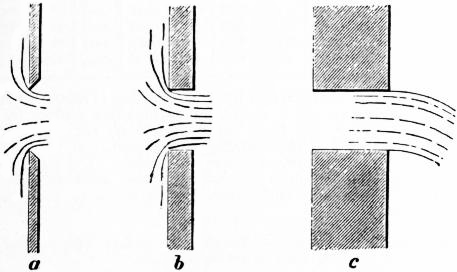
Coefficient of Contraction—Sharp-edged Orifices in Plane Surfaces.—When a jet issues from an aperture in a vessel, it may either spring clear from the inner edge of the orifice as at a or b (fig. 15), or it may adhere to the sides of the orifice as at c. The former condition will be found if the orifice is bevelled outwards as at a, so as to be sharp edged, and it will also occur generally for a prismatic aperture like b, provided the thickness of the plate in which the aperture is formed is less than the diameter of the jet. But if the thickness is greater the condition shown at c will occur.
When the discharge occurs as at a or b, the filaments converging towards the orifice continue to converge beyond it, so that the section of the jet where the filaments have become parallel is smaller than the section of the orifice. The inertia of the filaments opposes sudden change of direction of motion at the edge of the orifice, and the convergence continues for a distance of about half the diameter of the orifice beyond it. Let ω be the area of the orifice, and ccω the area of the jet at the point where convergence ceases; then cc is a coefficient to be determined experimentally for each kind of orifice, called the coefficient of contraction. When the orifice is a sharp-edged orifice in a plane surface, the value of cc is on the average 0.64, or the section of the jet is very nearly five-eighths of the area of the orifice.
 |
| Fig. 16. |
Coefficient of Discharge.—In applying the general formula Q = ωv to a stream, it is assumed that the filaments have a common velocity v normal to the section ω. But if the jet contracts, it is at the contracted section of the jet that the direction of motion is normal to a transverse section of the jet. Hence the actual discharge when contraction occurs is
or simply, if c = cvcc,
where c is called the coefficient of discharge. Thus for a sharp-edged plane orifice c = 0.97 × 0.64 = 0.62.
§ 18. Experimental Determination of v, cc, and c.—The coefficient of contraction cc is directly determined by measuring the dimensions of the jet. For this purpose fixed screws of fine pitch (fig. 16) are convenient. These are set to touch the jet, and then the distance between them can be measured at leisure.
The coefficient of velocity is determined directly by measuring the parabolic path of a horizontal jet.
Let OX, OY (fig. 17) be horizontal and vertical axes, the origin being at the orifice. Let h be the head, and x, y the coordinates of a point A on the parabolic path of the jet. If va is the velocity at the orifice, and t the time in which a particle moves from O to A, then
Eliminating t,
Then
In the case of large orifices such as weirs, the velocity can be directly determined by using a Pitot tube (§ 144).
 |
| Fig. 17. |
The coefficient of discharge, which for practical purposes is the most important of the three coefficients, is best determined by tank measurement of the flow from the given orifice in a suitable time. If Q is the discharge measured in the tank per second, then
Measurements of this kind though simple in principle are not free from some practical difficulties, and require much care. In fig. 18 is shown an arrangement of measuring tank. The orifice is fixed in the wall of the cistern A and discharges either into the waste channel BB, or into the measuring tank. There is a short trough on rollers C which when run under the jet directs the discharge into the tank, and when run back again allows the discharge to drop into the waste channel. D is a stilling screen to prevent agitation of the surface at the measuring point, E, and F is a discharge valve for emptying the measuring tank. The rise of level in the tank, the time of the flow and the head over the orifice at that time must be exactly observed.
For well made sharp-edged orifices, small relatively to the water surface in the supply reservoir, the coefficients under different conditions of head are pretty exactly known. Suppose the same quantity of water is made to flow in succession through such an orifice and through another orifice of which the coefficient is required, and when the rate of flow is constant the heads over each orifice are noted. Let h1, h2 be the heads, ω1, ω2 the areas of the orifices, c1, c2 the coefficients. Then since the flow through each orifice is the same
§ 19. Coefficients for Bellmouths and Bellmouthed Orifices.—If an orifice is furnished with a mouthpiece exactly of the form of the contracted vein, then the whole of the contraction occurs within the mouthpiece, and if the area of the orifice is measured at the smaller end, cc must be put = 1. It is often desirable to bellmouth the ends of pipes, to avoid the loss of head which occurs if this is


