focal length that rays parallel to the axis falling upon it were united exactly upon the object. In this case the object lay upon a stage plate, whose centre had so far been made opaque, so that the rays coming from the illuminating plane mirror could not reach the objective direct, but only the rays passing the stage plate to the side of this blackened portion reached the Lieberkühn mirror, and were used in lighting.
Fig. 43.—Vertical |
The disadvantage of this method was that only small opaque objects could be examined. Much more easily manipulated is the parabolic side-illuminator invented by R. Beck, which can be conveniently fitted in and used for objectives with different focal lengths. It consists in half of a short focused parabolic mirror, which concentrates all the light coming from the one side on to the object. To examine objects with objectives of high power and low free object distance, the apparatus for side-illumination is not sufficient, and a so-called vertical illuminator is used. In Zeiss's form (fig. 43) a small prism p, which also revolves upon a horizontal axis, is placed as near as possible to the back lens of the objective. The edge which is the separating line of the horizontal and hypothenuse surfaces of the prism, lies approximately over the middle of the system, so that the rays entering through the opening in the side after having been reflected by the hypothenuse surface are concentrated through one half of the objective on to the object. When observing only the other half of the objective is used. The sources of light used should be arranged so that the objective throws an image of the light-source upon the object. It is best if the image of the light is not larger than the object examined, and to effect this, an illuminating lens with an iris diaphragm is often placed between the source of light and the illuminator. By suitable adjustment and by changing the iris diaphragm the size of the illuminating field can be controlled. The objects observed with the vertical illuminator must not have a glass cover if the dry system is employed, because the upper surface of the glass cover would send so much light back into the objective by reflection, that the image would be indistinct. It is, on the contrary, possible to examine covered objects with the vertical illuminator, if the immersion system be employed. Owing to the slight difference of illumination between the immersion liquid and the cover, the portion of light reflected on the cover is not noticeable.
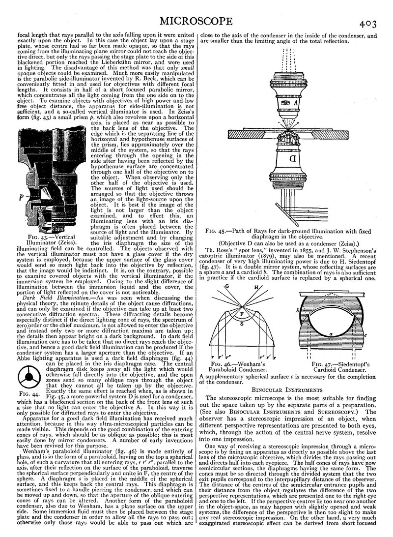
Dark Field Illumination.—As was seen when discussing the physical theory, the minute details of the object cause diffractions, and can only be examined if the objective can take up at least two consecutive diffraction spectra. These diffracting details become especially distinct if the direct lighting cone of rays, the spectrum of zero order or the chief maximum, is not allowed to enter the objective and instead only two or more diffraction maxima are taken up; the details then appear bright on a dark background. In dark field illumination care has to be taken that no direct rays reach the objective, and hence a good dark field illumination can be produced if the condenser system has a larger aperture than the objective. If an Abbe lighting apparatus is used a dark field diaphragm (fig. 44) can be placed in the iris diaphragm case. The central diaphragm disk keeps away all the light which would otherwise fall directly into the objective, and the open zones send so many oblique rays through the object that they cannot all be taken up by the objective. Exactly the same effect is reached when, as is shown in Fig. 45, a more powerful system D is used for a condenser, which has a blackened section on the back of the front lens of such a size that no light can enter the objective A. In this way it is only possible for diffracted rays to enter the objective.
Fig. 44. |
Apparatus for a good dark field illumination has received much attention, because in this way ultra-microscopical particles can be made visible. This depends on the good combination of the entering cones of rays, which should be as oblique as possible; this is most easily done by mirror condensers. A number of early inventions have been revived for this purpose.
Wenham’s paraboloid illuminator (fig. 46) is made entirely of glass, and is in the form of a paraboloid, having on the top a spherical hole, of such a curvature that all entering rays, r r ′ r ″, parallel to the axis, after their reflection on the surface of the paraboloid, traverse the spherical surface perpendicularly and unite in F, the centre of the sphere. A diaphragm s is placed in the middle of the spherical surface, and this keeps back the central rays. This diaphragm is sometimes fixed to a handle piercing the condenser, and which can be moved up and down, so that the aperture of the oblique entering cones of rays can be altered. Another form of the paraboloid condenser, also due to Wenham, has a plane surface on the upper side. Some immersion fluid must then be placed between the stage plate and the condenser in order to allow all the rays to pass out; otherwise only those rays would be able to pass out which are close to the axis of the condenser in the inside of the condenser, and are smaller than the limiting angle of the total reflection.
Fig. 45.—Path of Rays for dark-ground illumination with fixed
diaphragm in the objective.
(Objective D can also be used as a condenser (Zeiss).)
Th. Ross’s “spot lens,” invented in 1855, and J. W. Stephenson's catoptric illuminator (1879), may also be mentioned. A recent condenser of very high illuminating power is due to H. Siedentopf (fig. 47). It is a double mirror system, whose reflecting surfaces are a sphere a and a cardioid b. The combination of rays is also sufficient in practice if the cardioid surface is replaced by a spherical one.
| Fig. 46.—Wenham’s Paraboloid Condenser. |
Fig. 47.—Siedentopf’s Cardioid Condenser. |
A supplementary spherical surface c is necessary for the completion of the condenser.
Binocular Instruments
The stereoscopic microscope is the most suitable for finding out the space taken up by the separate parts of a preparation. (See also Binocular Instruments and Stereoscopy.) The observer has a stereoscopic impression of an object, when different perspective representations are presented to both eyes, which, through the action of the central nerve system, resolve into one impression.
One way of receiving a stereoscopic impression through a microscope is by fixing an apparatus as directly as possible above the last lens of the microscopic objective, which divides the rays passing out and dIrects half into each eyepiece. The half cones of rays have now semicircular sections, the diaphragms having the same form. The cones must be so directed through the divided system that the two exit pupils correspond to the interpupillary distance of the observer. The distance of the centres of the semicircular entrance pupils and their distance from the object regulates the difference of the two perspective representations, which are presented one to the right eye and one to the left. If the perspective centres lie too near one another in the object-space, as may happen with slightly opened and weak systems, the difference of the perspective is then too slight to make any real stereoscopic impression. On the other hand, a very much
exaggerated stereoscopic effect can be derived from short focused