the cylinder and the ports and passages leading to its ends. The
seat, or surface on which the valve slides, is a plane surface formed
on or fixed to the side of the cylinder, with three ports or openings
which extend across the greater part of the cylinder’s width. The
central opening is the exhaust port through which the steam
escapes; the others, or steam ports, which are narrower, lead to the
two ends of the cylinder respectively. The valve is a box-shaped
cover which slides over the seat, and the whole is enclosed in a
chamber called the valve-chest, to which steam from the boiler is
admitted. When the valve moves a sufficient distance to either
side of the central position, steam enters one end of the cylinder
from the valve-chest and escapes from the other end of the cylinder
through the cavity of the valve into the exhaust port. The valve
is generally moved by an eccentric on the engine shaft, which is
mechanically equivalent to a crank whose radius is equal to the 
Fig. 19.
eccentricity, or distance from the centre of the shaft to the centre
of the eccentric sheave. The eccentric rod is generally so long that
the motion of the valve is sensibly the same as that which it would
receive were the rod infinitely long. Thus if
a circle (fig. 19) be drawn to represent the path
of the eccentric centre during a revolution of
the engine, and a perpendicular PM be drawn
from any point P on a diameter AB, the distance
CM is the displacement of the valve from its
middle position at the time when the eccentric
centre is at P. AB is the whole travel of the
valve.
61. Lap and Lead.—If the valve when in its middle position did not overlap the steam ports (fig. 20), any movement to the right or the left would admit steam, and the admission would continue until the valve had returned to its middle position, or, in other words, for half a revolution of the engine. Such a valve would not serve for expansive working, and as regards the relative position of the crank and eccentric it would have to be set so that its middle position coincided with the extreme position of the piston; in other words, the eccentric radius would make a right angle with the crank.

| ||
| Fig. 20.—Slide-Valve without Lap. |
Fig. 21.—Slide-Valve with Lap. | |
Expansive working, however, becomes possible when we give the
valve what is called “lap,” by making it project over the edges of
the steam ports, as in fig. 21, where is the “outside lap” and 𝑖 is
the “inside lap.” Admission of steam (to either side) then begins
only when the displacement of the valve from its middle position
exceeds the amount of the outside lap, and continues only until the
valve has returned to the same distance from its middle position.
Further, exhaust begins only when the valve has moved past the
middle by a distance equal to 𝑖, and continues until the valve has
again returned to a distance 𝑖 from its middle position. Thus on
the diagram of the eccentric’s travel
(fig. 22) we find, by setting off 𝑜 and 𝑖 
Fig. 22.
on the two sides of the centre, the positions
𝑎, 𝑏, 𝑐 and 𝑑 of the eccentric radius
at which the four events of admission,
cut-off, release and compression occur
for one side of the piston. As to the
other side of the piston, it is only necessary
to set off 𝑜 to the right and 𝑖 to the
left of the centre, but for the sake of
clearness we may confine our attention
to one of the two sides. Of the whole
revolution, the part from 𝑎 to 𝑏 is the
arc of steam admission, from 𝑏 to 𝑐 is
the arc of expansion, from 𝑐 to 𝑑 the arc of exhaust, and from 𝑑 to
𝑎 the arc of compression. The relation of these, however, to the
piston’s motion is still undefined. If the eccentric were set in
advance of the crank by an angle equal to AC𝑎, the opening of the
valve would be coincident with the beginning of the piston’s stroke.
It is, however, desirable, in order to allow the steam free entry, that
the valve be already some way open when the piston stroke begins,
and thus the eccentric may be set to have a position C𝑎′ at the beginning
of the stroke. In that case the valve is open at the beginning
of the stroke to the extent 𝑚𝑚′, which is called the “lead.” The
amount by which the angle between C𝑎′ (the eccentric) and CA (the
crank) exceeds a right angle is called the angular advance, this being
the angle by which the eccentric is set in advance of the position it
would occupy if the primitive arrangement without lap were adopted.
The quantities lap, lead and angular advance (θ) are connected by
the equation
outside lap+lead=half travel ✕ cos θ.
An effect of lead is to cause preadmission, that is to say, admission before the end of the back stroke, which, together with the compression of steam left in the cylinder when the exhaust port closes, produces the mechanical effect of “cushioning,” to which reference has already been made. To examine the distribution of steam throughout the piston’s stroke, we may now draw a circle to represent the path of the crank pin (fig. 23, where the dotted lines have been added to show the assumed configuration of piston, connecting-rod and crank) and transfer to it from the former diagram the angular positions 𝑎, 𝑏, 𝑐 and 𝑑 at which the four events occur.

Fig. 23.
To facilitate this transfer the diagrams of eccentric path and of crank-pin path may by a suitable choice of scales be drawn of the same actual size. Then by projecting these points on a diameter which represents the piston’s path, by circular arcs drawn with a radius equal to the length of the connecting-rod, we find 𝑝, the position of the piston at which admission occurs during the back stroke, also 𝑞 and 𝑟, the position at cut-off and release, during the stroke which takes place in the direction of the arrow, and 𝑠, the point at which compression begins. It is obviously unnecessary to draw the two circles of figs. 22 and 23 separately; the single diagram (fig. 24) contains the solution of the steam distribution with a slide-valve whose laps, travel and angular advance are known, the same circle serving, on two scales, to show the motion of the crank and of the eccentric.
 |

| |
| Fig. 24. | Fig. 25. |
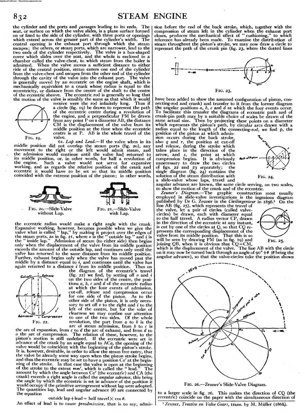
Zeuner’s Diagram.—The graphic construction most usually employed in slide-valve investigations is the ingenious diagram published by Dr G. Zeuner in the Civilingenieur in 1856.[1] On the line AB (fig. 25), which represents the travel of the valve, let a pair of circles (called valve-circles) be drawn, each with diameter equal to the half travel. A radius vector CP, drawn in the direction of the eccentric at any instant, is cut by one of the circles at Q, so that CQ represents the corresponding displacement of the valve from its middle position. That this is so will be seen by drawing PM (as in fig. 19) and joining QB, when it is obvious that CQ=CM, which is the displacement of the valve. The line AB with the circle on it may now be turned back through an angle of 90°+θ (θ being the angular advance), so that the valve-circles take the position shown to a larger scale in fig. 26.

Fig. 26.—Zeuner’s Slide-Valve Diagram.
This makes the direction of CQ (the eccentric) coincide on the paper with the simultaneous direction of
- ↑ Zeuner, Treatise on Valve Gears, trans, by M. Müller (1868).