The first person who succeeded in making one clock regulate or govern others by electricity, Mr R. L. Jones, accordingly abandoned the idea of electrical driving of one clock by another; and instead of making the electrical connection with a standard clock (whether itself an electrical one or not) drive the others, he makes it simply let the pallets or the pendulum of the subordinate clock, driven by a weight or spring, be influenced by attraction at every beat of the standard clock; and, by way of helping it, the pallets are made what we called half-dead in describing the dead escapement, except that they have no impulse faces, but the dead faces have just so much slope that they would overcome their own friction, and escape of themselves under the pressure of the clock train, except while they are held by the magnet, which is formed at every beat of the standard clock, or at every half-minute contact, if it is intended to work the dials by half-minute jumps. This plan has been extensively used for regulating distant clocks from Greenwich Observatory.
The first electrical clocks, in the proper sense of the term, were invented by Mr Bain in 1840, who availed himself of the discovery of Oersted that a coil of insulated wire in the form of a hollow cylinder is attracted in one direction or the other by a permanent magnet within the coil, not touching it, when the ends of the coil are connected with the poles of a battery; and if the connection is reversed, or the poles changed, so that the current at one time goes one way through the coil from the - or copper plate to the + or zinc plate, and at other times the other way, the direction of the attraction is reversed. Mr Bain made the bob of his pendulum of such a coil enclosed in a brass case so that it looked like a hollow brass cylinder lying horizontal and moving in the direction of its own axis, and in that axis stood the ends of two permanent magnets with the north poles pointed at each other and nearly touching, as in the right hand part of fig. 16. The pendulum pushed a small sliding bar backwards and forwards so as to reverse the current through the coil as the pendulum passed the middle of the arc, and so caused each magnet in turn to attract the bob. But this also failed practically, and especially in time-keeping, as might have been expected, from the friction and varying resistance of the bar to the motion of the pendulum, and in the attractions.
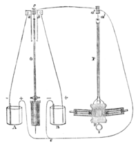
Mr Ritchie of Edinburgh, however, has combined the principle of Bain's and Jones's clocks in a manner which is testified to be completely successful in enabling one standard clock to control and keep going any number of subordinate ones, which do not require winding up as Jones's do, but are driven entirely by their pendulums. This differs from Wheatstone's plan in this, that his subordinate clocks had no pendulum swinging naturally and only wanting its vibrations helping a little, but the pallets had to be made to vibrate solely by the electrical force. The figures are taken from Mr Ritchie's paper read before the Royal Scottish Society of Arts in 1873. The controlled pendulum P is that just now described as Bain's (seen in fig. 17 the other way, across the plane of vibration); the rod and spring are double, and the wire cd is connected with one spring and rod (say the front one) and the wire d′e with the other; so that the current has to pass down one spring and one rod and through the coil in the bob and up the other spring. The other pendulum O of the normal or standard clock is a common one. except that it touches two slight contact springs a, b alternately, and so closes the circuit on one side and leaves it broken on the other. When that pendulum touches a the B battery does nothing, and the - current from the battery A passes by a to c and d and down the d spring and rod and up through d to e and back again to + of A. But when the standard pendulum O touches b the A battery does nothing, and the current from - to + of the B battery goes the other way, through the controlled pendulum and its coil. The two fixed magnets SN, NS consequently attract the coil and bob each way alternately. And even if the current is occasionally weak, the natural swing of the pendulum will keep it going for a short time with force enough to drive its clock through a reversed escapement; and further, if that pendulum is naturally a little too fast or too slow the attraction from the standard pendulums will retard or accelerate it. In practice, however, it is found better not to make the contact by springs, which, however light, disturb the pendulum a little, but by a wheel in the train making and breaking contact at every beat; and if the clock has a gravity escapement there is no danger of this friction affecting the pendulum at all.

Fig. 18.—Ritchie's Elliptical Escapement.


