Popular Science Monthly
��of the large wire nail that acts as a sort of a movable handle. The machine is set when the points of the arrows are exactly opposite. The lower wheel always turns from left to right. It is now ready for adding a column of figures. Take the figures 8, 9, 6, 9, 8, 7, 7, 9, 3 and 2 and add them. Insert the point of the wire nail in the indentation of the lower wheel opposite the number 8 of the board. Pay no attention to the numbers on the wheel until you finish adding. Turn the lower figure wheel with the nail until the point is opposite the guide line. Lift the nail and place the point in the indentation at number 9 of the board and turn the wheel until the nail is opposite the guide line. Again lift the nail, insert the point opposite the number 6 of the board and turn the wheel until the nail is once more opposite the guide line. Add the other figure in the same way. The sum total of the column will appear at the opposite ends of the guide lines, namely, 68.
The capacity of the machine is 100, but by keeping tally of how many times . the cog number 9 passes the guide line, you can use the machine for any column of figures. This machine is also a sub- tracting machine. To subtract with it, set the upper wheel so that the first digit of the minuend appears at the guide line, and then set the lower wheel so that the second digit of the minuend also appears at the guide line. Now place the nail opposite the subtrahend marked on the board and move the lower wheel clockwise — in the opposite direction to that indicated by the arrow — the number of spaces equal to the sub- trahend. As in addition, the result ap- pears at the guide lines. When there are two digits in the subtrahend place the nail in the hole opposite the digit on the board and, as in the first case, turn the wheel a number of spaces equal to the subtrahend.
The subtracting numbers of one digit, the zero mark on the upper, or tens, wheel raiust be set on the guide line, since the tens place is not represented in the minuend.
This machine is not difficult to make, and it will be found very convenient by anyone who does much figuring but not enough to warrant the purchase of a machine.— E. P. Thornton.
��7815
A Simple Sawdust Deflector for a Circular Saw Bench
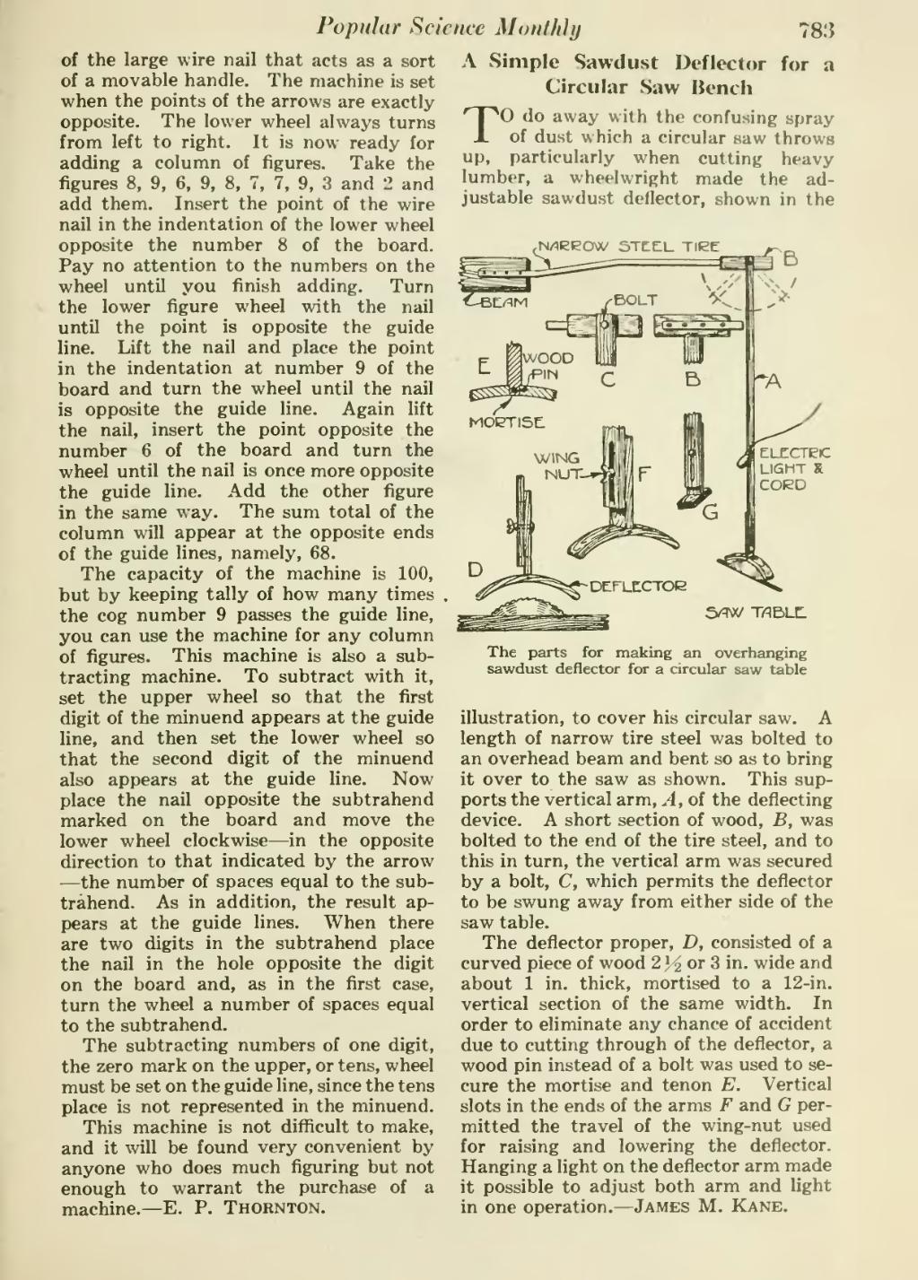
TO do away with the confusing spray of dust which a circular saw throws up, particularly when cutting heavy lumber, a wheelwright made the ad- justable sawdust deflector, shown in the
��rN/lEEOW STtElL TIEE
���5/qw T/qBLH
��The parts for making an overhanging sawdust deflector for a circular saw table
��illustration, to cover his circular saw. A length of narrow tire steel was bolted to an overhead beam and bent so as to bring it over to the saw as shown. This sup- ports the vertical arm. A, of the deflecting device. A short section of wood, B, was bolted to the end of the tire steel, and to this in turn, the vertical arm was secured by a bolt, C, which permits the deflector to be swung away from either side of the saw table.
The deflector proper, D, consisted of a curved piece of wood 2} 2 or 3 in. wide and about 1 in. thick, mortised to a 12-in. vertical section of the same width. In order to eliminate any chance of accident due to cutting through of the deflector, a wood pin instead of a bolt was used to se- cure the mortise and tenon E. Vertical slots in the ends of the arms F and G per- mitted the travel of the wing-nut used for raising and lowering the deflector. Hanging a light on the deflector arm made it possible to adjust both arm and light in one operation. — James M. Kane.
�� �