MICROSCOPE (Gr. μικρός, small, σκοπεῖν, to view), an optical instrument for examining small objects or details of such objects; it acts by making the angles of vision under which the images appear greater than when the objects themselves are viewed by the naked eye.
Microscopes are distinguished as simple and compound. A simple microscope consists of a single positive lens, or of a lens combination acting as a single lens, placed between the eye and the object so that it presents a virtual and enlarged image. The compound microscope generally consists of two positive lens systems, so arranged that the system nearer the object (termed the objective) projects a real enlarged image, which occupies the same place relatively to the second system (the eyepiece or ocular) as does the real object in the simple microscope. An image is therefore projected by the ocular from the real magnified image produced by the objective with increased magnification.
History of the Simple Microscope.—Any solid or liquid transparent medium of lenticular form, having either one convex and one flat surface or two convex surfaces whose axes are coincident, may serve as a “magnifier,” the essential condition being that it shall refract the rays which pass through it so as to cause widely diverging rays to become either parallel or but slightly divergent. Thus if a minute object be placed on a slip of glass, and a single drop of water be placed upon it, the drop will act as a magnifier in virtue of the convexity of its upper surface; so that when the eye is brought sufficiently near it (the glass being held horizontally) the object will be seen magnified. Again if a small hole be made in a thin plate of metal, and a minute drop of water be inserted in it, this drop, having two convex surfaces, will serve as a still more powerful magnifier. There is reason to believe that the magnifying power of transparent media with convex surfaces was very early known. A convex lens of rock-crystal was found by Layard among the ruins of the palace of Nimrud; Seneca describes hollow spheres of glass filled with water as being commonly used as magnifiers.
The perfect gem-cutting of the ancients could not have been attained without the use of magnifiers; and doubtless the artificers who executed these wonderful works also made them. Convex glass lenses were first generally used to assist ordinary vision as “spectacles”; and not only were spectacle-makers the first to produce glass magnifiers (or simple microscopes), but by them also the telescope and the compound microscope were first invented. During the Thirty Years’ War the simple microscope was widely known. Descartes (Dioptrique, 1637) describes microscopes wherein a concave mirror, with its concavity towards the object, is used, in conjunction with a lens, for illuminating the object, which is mounted on a point fixing it at the focus of the mirror. Antony van Leeuwenhoek appears to be the first to succeed in grinding and polishing lenses of such short focus and perfect figure as to render the simple microscope a better instrument for most purposes than any compound microscope then constructed. At that time the “compass” microscope was in use. One leg of a compass carried the object, and the other the lens, the distance between the two being regulated by a screw. Stands were also in use, permitting the manipulation of the object by hand. Robert Hooke shaped the minutest of the lenses with which he made many of the discoveries recorded in his Micrographia from small glass globules made by fusing the ends of threads of spun glass; and the same method was employed by the Italian Father Di Torre. Early opticians and microscopists gave their chief attention to the improvement of the simple microscope, the principle of which we now explain.
Simple Microscope
Position and Size of the Image.—A person with normal vision can see objects distinctly at a distance varying from ten, inches to a very great distance. Objects at different distances, however, are not seen distinctly simultaneously, but in succession. This is effected by the power of accommodation of the eye, which can so alter the focal length of its crystalline lens that images of objects at different distances can be produced rapidly and distinctly one after another upon the retina.
The angle under which the object appears depends upon the distance and size of the object, or, in other words, the size of the image on the retina is determined by the distance and the dimensions of the object. The ratio between the real size of the object y (fig. 1)

Fig. 1.
and the distance l, which is equal to the tangent of the visual angle w, is termed the “apparent size” of the object. From the figure, which represents vision with a motionless eye, it is seen that the apparent size increases as the object under observation is approached. The greater the visual angle, the more distinctly are the details of the object perceived. On the other hand, as the observer recedes from the object, the apparent size, and also the image on the retina diminishes; details become more and more confused, and gradually, after a while, disappear altogether, and ultimately the external configuration of the object as a whole is no longer recognizable. This case arises when the visual angle, under which the object appears, is approximately a minute of arc; it is due to the physiological construction of the retina, for the ends of nerve fibres, which receive the impression of light, have themselves a definite size. The lower limit of the resolving power of the eye is reached when the distance is approximately 3438 times the size of the object. If the object be represented by two separate points, these points would appear distinct to the normal eye only so long as the distance between them is at the most only 3438 times smaller than their distance from the eye. When the latter distance is increased still further, the two appear as one. Therefore when it is desired to distinctly recognize exceedingly small objects or details of such, they are brought as near as possible to the eye. The eye is strained in bringing its focal length to the smallest possible amount, and when this strain is long continued it may cause pain. When the shortest distance obtained by the highest strain of accommodation is insufficient to recognize small objects, distinct vision is possible at even a shorter distance by placing a very small diaphragm between the eye and the object, the pencils of rays proceeding from the object-points, which otherwise are limited by the pupils of the eye, being thus restricted by the, diaphragm. The object is then projected with such acute pencils on the plane focused for, in this case on the plane on which the eye can just accommodate itself, that the circle of confusion arising there is still so small that it is below the limit of angular visual distinctness and on that account appears as a sharp point. However, the loss of light in this procedure is extraordinarily large, so that only most intensely illuminated objects can be investigated.
A naked short-sighted eye, which would be corrected for distant objects by a spectacle glass of −10 diopters, may approach the object up to about 4 in. and have a sharp image upon the retina without any strain whatever. For the observation of small objects, a myopic eye is consequently superior to a normal eye; and the normal eye in its turn is superior to the hypermetropic one. When the details are no longer recognizable by the unaided eye, the magnifying glass or the simple microscope is necessary. As a rule large magnification is not demanded from the former, but a larger field of view, whilst the simple microscope should ensure powerful magnification even when the field is small. The simple microscope enlarges the angle of vision, and does not tire the eye when it is arranged so that the image lies in the farthest limit of distinct vision (the punctum remotum). A normal eye will therefore see an image formed by the magnifying glass most conveniently when it is produced at a great distance, i.e.. when the object is in its front focal plane.

Fig. 2.
If y (fig. 2) be the object the image appears to a normal eye situated behind the system L with passive accommodation at a very great distance under the angle w ′. Since H′ P=F O,=y, from the focal length of the simple microscope, the visual angle w′ is given by
| tan w ′/y=1/f ′=V, | (1) |
in which f ′, = H′ F′, is the image-side focal length (see Lens). Since the lens is bounded by air, the image- and object-side focal lengths f ′ and f are equal. The value 1/f ′ or V in (1), is termed the power of the lens. In most cases the number of “diameters” of the simple microscope is required; i.e. the ratio between the apparent sizes of the object when observed through the microscope and when viewed by the naked eye. When a person of normal vision views a small object, he brings it to the distance of distinct vision, which would average about 10 in. The apparent size is then (fig. 1) tan w=y/l, where l=10 in., whilst the apparent size of the object viewed through the magnifying glass would result from the formula (1) tan w ′ =y/f. Consequently the number of diameters will be
| N=tan w ′/tan w=y/f . l/y=l/f=V.l; | (2) |
it is thus equal to the magnifying power multiplied by the distance of distinct vision, or the number of times that the focal length is contained in 10 in.
Since this value for the distance of distinct vision is only conventional, it is understood that the capacity of the simple microscope given in (2) holds good only for eyes accustomed to examine small objects 10 in. away; and observation through the magnifying glass must be undertaken by the normal eye with passive accommodation. A lens of 1 in. focal length must be spoken of, according to this notation, as a × 10 lens, and a lens of 110 in. focal length as a × 100 lens. Obviously the position of a normal eye free from accommodation is immaterial for determining the magnification. A × 10 magnification is, however, by no means guaranteed to a myopic eye of −10 D by a lens of 1 in. focus. Since this shortsighted observer can view the object with the naked eye with no inconvenience to himself, at 4 in. distance, it follows (to him) the apparent size is tan w=y/4; and to secure convenient vision through the lens the short-sighted person would bring the object to such a distance that a virtual, magnified image would be projected in his punctum remotum. In addition it will be supposed that the centre of the pupil of the observer coincides with the back focal point of the system. The apparent size of the object seen through the lens is then tan w ′=y/f. The magnification, resulting from the simple microscope of 1 in. focus, is here N=tan w ′/tan w=y/f.4/y=4/f=4. Thus, while a lens of 1 in. focal length assures to the normal-sighted person a × 10 magnification, it affords to the short-sighted individual only × 4. On the other hand, it is even of greater use to the hypermetropic than to the observer of normal sight. From this it appears that each observer obtains specific advantages from one and the same simple microscope, and also the individual observer can obtain different magnifications by either using different accommodations, or by viewing in passive accommodation.
Regulation of the Rays.[1]—In using optical instruments the eye in general is moved just as in free vision; that is to say, the attention is fixed upon the individual parts of the image one after another, the eye being turned in its cavity. In this case the eye is always directed so that the part of the image which is wished to be viewed exactly falls upon the most sensitive portion of the retina, viz. the macula lutea (yellow spot). Corresponding to the size of the yellow spot only a small fraction of the image appears particularly distinctly. The other portions which are reproduced on the retina on the regions surrounding the yellow spot will also be perceived, but with reduced definition. These external and less sensitive parts of the retina, therefore, merely give information as to the general arrangement of the objects and to a certain extent act as guide-post in order to show quickly and conveniently, although not distinctly, the places in the image which should claim special attention. Vision with a motionless eye, or “indirect vision,” gives a general view over the whole object with particular definition of a small central portion. Vision with a movable eye, or “direct vision,” gives exact information as to the parts of the object one after another.
The simple microscope permits such vision. If the instrument has a sensible lens diameter, and is arranged so that the centre of rotation of the eye can coincide with the intersection of the principal rays, the lens can then form with the eye a centred system. Such lenses are termed “lenses for direct vision.” By moving the eye about its centre of rotation M the whole field can be examined. The margin of the mount of the lens serves as the diaphragm of the field of view. The selection of the rays emerging from the lens and actually employed in forming the image is undertaken by the pupil of the eye which, in this case, is consequently the exit pupil of the instrument.

Fig. 3.
In fig. 3 P′P′1 designates the exit pupil of the lens, and the image of P′P′1, i.e. PP1, which is formed by the lens, limits the aperture of the pencils of rays on the object-side; consequently it is the entrance pupil of the instrument. Since the exit pupil moves in observing the whole field, the entrance pupil also moves. The principal rays, which on the object-side connect the object-points with the centre of the entrance pupil, intersect the axis on the image-side at the centre of rotation M of the eye. M is therefore the intersection of the principal rays.
So long as the exit pupil is completely filled the brightness of the image will be approximately equal to that of free vision. If, however, we fix the points lying towards the margin of the field of view, the diaphragm gradually cuts off more and more of the rays which were necessary to fill the pupil, and in consequence the brightness gradually falls off to zero. This vignetting can be observed in all lenses.

Fig. 4.
In most cases, and also in corrected systems, the intersection of
the principal rays is no longer available for the centre of rotation
of the eye, and this kind of observation is impossible.
In some instruments observation of the whole available field is only possible when the head and eye are moved at the same time, the lens retaining its position. Dr M. von Rohr terms this kind of vision “peep-hole observation.” It has mainly to be considered in connexion with powerful magnifying glasses. In most cases a diaphragm regulates the rays. Fig. 4 shows the position of the diaphragms to be considered in this kind of observation. PP1 is the entrance pupil, P′P1′ the exit pupil, and GG the diaphragm. The intersection of the principal rays in this case lies in the middle of the entrance pupil or of the exit pupil. By head and eye motion the various parts of the whole field can be viewed one after another. The distance of the eye from the lens is here immaterial. In this case also the illumination must fall to zero by the vignetting of the pencils coming from objects at the margin of the field of view. C and D are the outermost rays which can pass through the instrument.
Magnifying glasses are often used for viewing three-dimensional objects. Only points lying on the plane focused for can be sharply reproduced in the retina, which acts as object-plane to the retina. All points lying out of this plane are reproduced as circles of confusion. The central projection, of which the centre is the middle point of the entrance pupil on the plane focused for, will show in weaker systems, or those very much stopped down, a certain finite depth of definition; that is to say, the totality of points, which lie out of the plane focused for, and which are projected with circles of confusion so small that they appear to the eye as sharp points, will include the sharp object relief, and determine the depth of definition of the lens. With increasing magnification the depth of definition diminishes, because the circles of confusion are greater in consequence of the shorter focal length. Very powerful simple microscopes have hardly any depth of definition so that in fact only points lying in one plane can be seen sharply with one focusing.
Illumination.—So long as the pupil of the observer alone undertakes the regulation of the rays there is no perceptible diminution of illumination in comparison with the naked eye vision. The losses of light which occur in this case are due to reflection, which takes place in the passage of the light through the glass surfaces. In a lens with two bounding surfaces in air there is a loss of about 9%; and in a lens system consisting of two separated lenses, »i.e. with four surfaces in air, about 17%. Losses due to absorption are almost zero when the lenses are very thin, as with lenses of small diameter. A very marked diminution in illumination occurs, however, when the exit pupil of the instrument is smaller than the pupil of the eye. In such instruments an arrangement is often required to intensely illuminate the object.
Forms of the Simple Microscope.—If the ordinary convex lens be employed as magnifying glass, great aberrations occur even in medium magnifications. These are: (1) chromatic aberration, (2) spherical aberration and (3) astigmatism (see Aberration).
When the pupil regulates the aperture of the rays producing the image the aberrations of the ordinary lenses increase considerably with the magnification, or, what 'amounts to the same thing, with the increase in the curvature of the surfaces. For lenses of short focus the diameter of the pupil is too large, and diaphragms must be employed which strongly diminish the aperture of the pencils, and so reduce the errors, but with a falling off of illumination. To reduce the aberrations Sir David Brewster proposed to employ in the place of glass transparent minerals of high refractive index and low dispersion. In this manner lenses of short focus can be produced having lower curvatures than glass lenses necessitate. The diamond has the requisite optical properties, its index of refraction being about 1·6 times as large as that of ordinary glass. The spherical aberration of a diamond lens can be brought down to one-ninth of a glass lens of equal focus. Apart, however, from the cost of the mineral and its very difficult working, a source of error lies in its want of homogeneity, which often causes a double or even a triple image. Similar attempts made by Pritchard with sapphires were more successful. With this mineral also spherical and chromatic aberration are a fraction of that of a glass lens, but double refraction, which involves a doubling of the image, is fatal to its use. Improvements in glass lenses, however, have rendered further experiments with precious stones unnecessary. The simplest was a sphere of glass, the equator of which (i.e. the mount) formed the diaphragm. Wollaston altered this by taking two plano-convex lenses, placing the plane surfaces towards each other and employing a diaphragm between the two parts (fig. 5).
| Wollaston. | Brewster. | Brewster (Stanhope). |
 |
 |
|
| Fig. 5. | Fig. 6. | Fig. 7. |
Sir David Brewster found that Wollaston’s form worked best when the two lenses were hemispheres and the central space was filled up with a transparent cement having the same refractive index as the glass; he therefore used a sphere and provided it with a groove at the equator (see fig. 6). Coddington employed the same construction, and for this reason this device is frequently called the Coddington lens; although he brought the Wollaston-Brewster lens into general notice, he was neither the inventor nor claimed to be. This lens reproduced all points of a concentric spherical surface simultaneously sharp. A construction also employing one piece of glass forms the so-called Stanhope lens (fig. 7), which was really due to Brewster. This is a glass cylinder, the two ends of which are spherical surfaces. The more strongly curved surface is placed next the eye, the other serves at the same time as specimen carrier. This lens is employed in articles found in tourist resorts as a magnifying glass for miniature photographs of the locality.
Doublets, &c.—To remove the errors which the above lenses showed, particularly when very short focal lengths were in question, lens combinations were adopted. The individual components required weaker curvatures and permitted of being more correctly manufactured, and, more particularly, the advantage of reduced aberrations was the predominant, factor.
Wollaston’s doublet (fig. 8) is a combination of two plano-convex lenses, the focal lengths of which are in the ratio of 3 : 1; the plane
| Wollaston. | Fraunhofer. | Wilson. | Steinheil. | Chevalier (Brücke). |
 |
 |
 |
 |

|
| Fig. 8. | Fig. 9. | Fig. 10. | Fig. 11. | Fig. 12. |
sides are turned towards the object, and the smaller of the two lenses is nearer the object. This construction was further improved (1) by introducing a diaphragm between the two lenses; (2) by altering the distance between the two lenses; and (3) by splitting the lower lens into two lenses. Triplets are employed when the focal length of the simple microscope was less than 110 in. When well made such constructions are almost free from spherical aberration, and the chromatic errors are very small. Similar doublets composed of two plano-convex lenses are the Fraunhofer (fig. 9) and the Wilson (fig. 10). Axial aberration is reduced by distributing the refraction between two lenses; and by placing the two lenses farther apart the errors of the pencils of rays proceeding from points lying outside the axis are reduced. The Wilson has a greater distance between the lenses, and also a reduction of the chromatic difference of magnification, but compared with the Fraunhofer it is at a disadvantage with regard to the size of the free working distance, i.e. the distance of the object from the lens surface nearer it.
By introducing a dispersive lens of flint the magnifying glass could be corrected for both chromatic and spherical aberrations. Browning’s “platyscopic” lens and the Steinheil “aplanatic” lens (fig. 11) are of this type. Both yield a field of good definition free from colour.
The manner in which the eye uses such a lens was first effectively taken into account by M. von Rohr. These anastigmatic lenses, which are manufactured up to × 40, are chromatically and spherically corrected, and for a middle diaphragm the errors of lateral pencils, distortion, astigmatism and coma are eliminated. “Peephole” observation is employed, observation being made by moving the head and eye while the lens is held steady. Even in powerful magnifications a good image exists in all parts of a relatively large field, and the free working distance is fairly large.
For especially large free working distances the corrections proposed by Chevalier and carried out by E. Brücke must be noticed (fig. 12). To an achromatic collective lens, which is turned towards the object, a dispersive lens is combined (this type to a certain extent belongs to the compound microscope). By altering the distance of the collective and dispersive members the magnification can be widely varied. Through the large free working distance, which for certain work offers great advantages, the size of the field of View is diminished.
In magnifying glasses for direct vision the eye must always be considered. The lens is brought as close as possible to the eye so as to view as large a field as possible. The watchmaker’s glass is one of the earliest forms of this kind. Gullstrand showed how to correct these lenses for direct vision, i.e. to eliminate distortion and astigmatism when the centre of rotation of the eye coincided with the point where the principal rays crossed the axis. Von Rohr fulfilled this condition by constructing the Verant lens, which are low power systems intended for viewing a large flat field.
Stands.—For dissecting or examining objects it is an advantage to have both hands free. Where very short focus simple microscopes are employed, using high magnifications, it is imperative to employ a stand which permits exact focusing and the use of a special illuminating apparatus. Since, however, only relatively low powers are now employed, the ordinary rack and pinion movement for focusing suffices, and for illuminating the object only a mirror below the stage is required when the object is transparent, and a condensing lens above the stage when opaque.
Dissecting stands vary as to portability, the size of the stand, and the manner in which the arm-rests are arranged. A stand is shown in fig. 57 (Plate). On the heavy horseshoe foot is a column carrying the stage. In the column is the guide for the rack-and-pinion movement. Lenses of various magnifications can be adapted to the carrier and moved about over the stage. The rests can be attached to the stage, and when done with folded together. Illumination of transparent objects is effected by the universal-jointed mirror. By turning the knob A, placed at the front corner of the stage, a black or white plate, forming a dark or light background, can be swung underneath the specimen.
When the recognition of the arrangement in space of small objects is desired a stereoscopic lens can be used. In most cases refracting and reflecting systems are arranged so that the natural interpupillary distance is reduced. Stereoscopic lenses can never be powerful systems, for the main idea is the recognition of the depth of objects, so that only systems having a sufficient depth of definition can be utilized. Very often such stereoscopic lenses, owing to faulty construction, give a false idea of space, ignoring the errors which are due to the alteration of the inter-pupillary distance and the visual angles belonging to the principal rays at the object-side (see Binocular Instruments).
Compound Microscope
 |
| Fig. 13.—Ray transmission in compound microscope with a positive ocular. |
| L1=objective, L2 L3=eyepiece of the Ramsden type. |
| F1, F1′=object- and image-side foci of objective. |
| F2=front focus of eyepiece. |
| P′P1′=exit pupil of objective. |
| P″P1″=exit pupil of complete microscope. |
| D D=diaphragm of field of view. |
The view held by early opticians, that a compound microscope could never produce such good images as an instrument of the simple type, has proved erroneous; and the principal attention of modern opticians has been directed to the compound instrument. Although we now know how the errors of lenses may be corrected, and how the simple microscope may be improved, this instrument remains with relatively feeble magnification, and to obtain stronger magnifications the compound form is necessary.
By compounding two lenses or lens systems separated by a definite interval, a system is obtained having a focal length considerably less than the focal lengths of the separate systems. If f and f ′ be the focal lengths of the combination, f1, f1′ and f2, f2′ the focal lengths of the two components, and Δ the distance between the inner foci of the components, then f=−f1f2/Δ, f ′f1′ f2′/Δ (see Lens). Δ is also equal to the distance F1′F2. The accented f ′s are always on the image side, whilst the unaccented are on the object side. From this formula it follows, for example, that one obtains a system of 18 in. focal length by compounding two positive systems of 1 in. each, whose focal planes, turned towards one another, are separated by 8 in.
A microscope objective being made in essentially the same Way as a simple microscope, and the front focus of the compound system being situated before the front focus of the objective, the magnification due to the simple system makes the free object distance greater than that obtained with a simple microscope of equal magnification. Moreover, this distance between the object and eye is substantially increased in the compound microscope by the stand; the inconveniences, and in certain circumstances also the dangers, to the eye which may arise, for example by warming the object, are also avoided. The convenient and rapid change in the magnification obtained by changing the eyepiece or the objective is also a special advantage of the compound form.
In the commonest compound microscopes, which consist of two positive systems a real magnified image is produced by the objective. This permits researches which are impossible with the simple microscope. For example, the real image may be recorded on a photographic plate; it may be measured; it can be physically altered by polarization, by spectrum analysis of the light employed by absorbing layers, &c. The greatest advantage of the compound microscope is that it represents a larger area, and this much more completely than is possible in the simple form. According to the laws of optics it is only possible either to portray a small object near one of the foci of the system with wide pencils, or to produce an image from a relatively large object by correspondingly narrow pencils. The simple microscope is subject to either limitation. As we shall see later, one of the principal functions of the microscope objective is the representation with wide pencils. In that case, however, in the compound microscope a small object may always be represented by means of wider pencils, one of the foci of the objective (not of the collective system) being near it. For the eyepiece the other rule holds; the object is represented by narrow pencils, and it is hence possible to subject the relatively great object, viz. the magnified real image, to a further representation.
History of the Compound Microscope.—The arrangement of two lenses so that small objects can be seen magnified followed soon after the discovery of the telescope. The first compound microscope (discovered probably by the Middelburg lens-grinders, Johann and Zacharias Janssen about 1590) was a combination of a strong biconvex with a still stronger biconcave lens; it had thus, as well as the first telescope, a negative eyepiece. In 1646 Fontana described a microscope which had a positive eyepiece. The development of the compound microscope essentially depends on the improvement of the objective; but no distinct improvement was made in its construction in the two centuries following the discovery. In 1668 the Italian Divini employed several doublets, i.e. pairs of plano-convex lenses, and his example was followed by Griendl von Ach. But even with such moderate magnification as these instruments permitted many faults were apparent. A microscope, using concave mirrors, was proposed in 1672 by Sir Isaac Newton; and he was succeeded by Barker, R. Smith, B. Martin, D. Brewster, and, above all, Amici. More recently these catadioptric microscopes were disregarded because they yielded unfavourable results. From 1830 onwards many improvements were made in the microscope objective; these may be best followed from a discussion of the faults of the image.
Position and Size of Image:—In most microscopic observations the object is mounted on a plane glass plate or slide about 0·06 in. thick, embedded in a liquid such as water, glycerine or Canada balsam, and covered with a plane glass plate of about 0·008 to 0·006 in. thick, called the cover-slip. If we consider the production of the image of an object of this kind by the two positive systems of a compound microscope shown in fig. 13, the objective L1 forms a real magnified image O′O1′; the object OO1, must therefore lie somewhat in front of the front focus F1 the objective. Let OO1=y, O′O1′=y ′, the focal distance of the image F1′O′=Δ and the image-side focal length f1′, then the magnification
| M=y ′/y=Δ/f1′ | (3) |
The distance A is called the “optical tube length.”
Weak and strong microscope objectives act differently. Weak systems act like photographic objectives. In this case the optical tube length may be altered within fixed limits without spoiling the image; at the same time the objective magnification M is also altered. This change is usually effected by mounting the objective and eyepiece on two telescoping tubes, so that by drawing apart or pushing in the tube length is increased or diminished at will. For strong objectives there is, however, only one optical tube length in which it is possible to obtain a good image by means of wide pencils, any alteration of the tube length involving a considerable spoiling of the image. This limitation is examined; below.
When forming an image by a microscope objective it often happens that the transparent media bounding the system have different optical properties. A series of objectives with short focal lengths are available, which permit the placing of a liquid between the cover-slip and the front lens of the objective; such lenses are known as “immersion systems”; objectives bounded on both sides by air are called “dry systems.” The immersion liquids in common use are water, glycerine, cedar-wood oil, monobromnaphthalene, &c. Immersion systems in which the embedding liquid, cover-slip, immersion-liquid and front lens have equal refractive indices are called “homogeneous immersion systems.” In immersion systems the object-side focal length is greater than the image-side focal length. Nothing is altered as to objective magnification, however, as the first surface is plane, and the employment of the immersion means that the value of f1′ is unaltered.
If we assume that a normal eye observes the image through the eyepiece, the eyepiece must project a distant image from the real image produced by the objective. This is the case if the image O′O1′ lies in the front focal plane of the eyepiece. In this case the optical tube length equals the distance of the adjacent focal planes of the two systems, which equals the distance of the image-side focus of the objective F1′ from the object-side focus of the eyepiece F2. The image viewed through the eyepiece appears then to the observer under the angle w″, and as with the single microscope
| tan w″/y′=1/f2′ | (4) |
where f ′2 is the image-side focal length of the eyepiece. To obtain the magnification of the complete microscope we must combine the objective magnification M with the action of the eyepiece. If we replace y ′ in equation (4) by the value given by (3), we obtain
| tan w ″/y=Δ/f1′. 1/f2″=V, | (5) |
the magnification of the complete microscope. The magnification therefore equals the power of the joint system.
The magnification is also expressed as the ratio of the apparent size of the object observed through the microscope to the apparent size of the object seen with the naked eye. As the conventional distance for clear vision with naked eye is 10 in., it results from fig. 1 that the apparent size is tan w=y/l. If this value of y be inserted in equation (5), we obtain the magnification number of the compound microscope:—
| N=tan w″/ tan w=Δl/f1f2′=Vl. | (6) |
 |
Fig. 14.—Ray transmission in compound microscope with a negative eyepiece.
L1=weak achromatic objective. L2=negative eyepiece. F1, F1′=object- and image-side foci of objective. F2, F2′=object- and image-side foci of eyepiece. P′P1′=exit pupil of objective. P″P1′=virtual image of P1P1′=exit pupil of complete microscope.
|
The magnification number increases then with the optical tube-length and with the diminution of the focal lengths of objective and eyepiece.
As with the simple microscope, different observers see differently in the same compound microscope; and hence the magnification varies with the power of accommodation.
The image produced by a microscope formed of two positive systems (fig. 13) is inverted, the objective L1 tracing from the object OO1 a real inverted image O′O′1, and the eyepiece L2L3 maintaining this arrangement. For many purposes it is immaterial whether the image is inverted or upright; but in some cases an upright image lightens the work, or may be indispensable.
The simplest microscope which produces an upright image has a negative lens as eyepiece. As shown in fig. 14, the real image formed by the objective must fall on the object-side focal plane of the eyepiece F2, where a normal eye without accommodation can observe it. But as the object-side focus F2 lies behind the eyepiece, the real image is not produced, but the converging pencils from the objective are changed by the eyepiece into parallels; and the point O1 in the top of the object y appears at the top to the eye, i.e. the image is upright.
The erection of inverted images by prisms, which was applied to the simple telescope by Porro, and to the binocular (q.v.) by A. A. Boulanger was employed by K. Bratuscheck in the Greenough double microscope; these (inverting prisms permit a convenient adaptation of the instrument to the interpupillary distance of the observer. Double microscopes, which produce a correct impression of the solidity of the object, must project upright images. The terrestrial eyepiece (see Telescope), which likewise ensures an upright image, but which involves an inconvenient lengthening, has also been employed in the binocular microscope.
Regulation of the Rays.—Weak and medium microscope objectives work like photographic objectives in episcopic or diascopic projection; in the microscope, however, the projected image is not intercepted on a screen, but a real image in air is formed. This must lie in the front focal plane of the eyepiece if we retain the supposition that it is to be viewed by a normal eye with passive accommodation. The plane in the object conjugate to the focal plane of the eye-piece is the plane focused for; and all points in it are sharply portrayed (a perfect objective being assumed). Object points lying out of the focal plane, on the other hand, are projected as circles of confusion on the plane focused for, the centre of the entrance pupil being the centre of projection and the circles of confusion constituting, with the points of the focal plane, the object-side imago. As the pencils used in the representations are of wide aperture on the object-side, only such points as are proportionately very near the focal plane can produce such small dispersion circles on the plane focused for, that they, so far as the objective- and eyepiece-magnification permit, appear as points to the eye. It follows that the depth of definition of the microscope is in general very trifling. As it is entirely a function of the aperture and the magnification, it can be increased by diminishing the entrance pupil, the magnification remaining unchanged. A diminution of the aperture, however, would injure a very much more important property, viz. the resolving power (see below). With powerful systems, object-points lying quite near the plane focused for would be represented by such large dispersion circles that practically only the points lying in one plane appear simultaneously sharp; and it is only by varying the Focus that the object-points lying in other planes can be observed.
The position of the diaphragm limiting the pencils proceeding from the object-points is not constant in the compound microscope. In all microscopes the rays are limited, not in the eyepiece, but in the objective, or before the objective when using a condenser. If the pencils are limited in the objective, the restriction of the pencil proceeding from the object-point is effected by either the front lens itself, by the boundary of a lens lying behind, by a real diaphragm placed between or behind the objective, or by a diaphragm-image.
The centre of the entrance pupil is the point of intersection of the principal rays; and it is therefore determinative for the perspective representation on the plane focused for. In fig. 15 the centre of the entrance pupil lies behind the focal plane, and consequently nearer objects appear larger, and farther objects smaller (“entocentric transmission,” see below).
 |
| (After M. v. Rohr.)
Fig. 15.—Entocentric transmission through a microscope objective. |
| E=plane focused for; O1*, O2*=projections of O1O2 on E; Z=centre of projection; P P1=a virtual image of real diaphragm P′P1′ with regard to the preceding part of the objective is the entrance pupil. |
If a diaphragm lying in the back focal plane of the objective forms the exit pupil for the objective, as in figs. 13 and 14, so that its image, the entrance pupil, lies at infinity, all the principal rays in the object-space are parallel to the axis, and we have on the object-side “telecentric” transmission. The size of the imago on the focal plane is always equal to its actual size, and is independent of the distance of the object from the plane focused for. This representation acquires a special importance if the object be micrometrically measured, for an inaccuracy in focusing does not involve an alteration of the size of the image. To ensure the telecentric transmission, the diaphragm in the back focus of the objective may be replaced by a diaphragm in the front focal plane of the condenser, supposing that uniformly illuminated objects are being dealt with; for in this case all the principal rays in the object-space are transmitted parallel to the axis.
With uniformly illuminated objects it may happen that the pencil in the object-space may be limited before passing the object, either through the size of the source of light employed or through a diaphragm connected with the illuminating system. In fig. 16 the intersection of the principal rays lies in front of the object, and consequently objects in front of the plane focused for will be projected on E magnified and the objects lying behind it diminished (“hypercentric” transmission). It produces a perspective representation entirely opposed to ordinary vision. As objects lying near us appear smaller in the case of hypercentric transmission than those lying farther from us, we receive a false impression of the spatial arrangement of the object.

|
| (After M. v. Rohr.) |
Fig. 16.—Hypercentric transmission in a microscope
objective. |
Whether the entrance pupil be before or behind the object, in general its position is such that it lies not too near the object, so that the principal rays will have in the object space only trifling inclinations towards one another or are strictly parallel. This is specially important, for otherwise pencils from points placed somewhat laterally to the axis arrive with diminished aperture at the image.
We see from fig. 13 that the objective’s exit pupil P′P1′ is portrayed by the positive eyepiece, the image P″P1″ limits the pencils proceeding from the eyepiece. This image P″P1″ is then the exit pupil of the combined system, and consequently the image of the entrance pupil of the combined system. As the exit pupil P′P1′ for the objective lies before the front focus of the eyepiece, generally at some distance and near the objective, the eyepiece projects a real image from it behind its image-side focus, so that if this point is accessible it is the exit pupil P″P1″. If, e.g. in the object-space the objective has telecentric transmission, the exit pupil must coincide with the back focal plane of the combined system, and it always lies behind the image-side focus of the eyepiece. The exit pupil, often called Ramsden’s circle, is thus accessible to the observer, who by head- and eye-movements may survey the whole field.
We can now understand the ray transmission in the compound microscope, shown in fig. 13. Points of a small object (compared with the focus of the objective) send to the objective wide pencils. The diaphragm limiting them, i.e. the entrance pupil, is placed so that the principal rays are either parallel or slightly inclined. The pencils producing the real image are very much more acute, and their inclination is the smaller the stronger the magnification. The eyepiece, which by means of narrow pencils represents the relatively large real image at infinity, transmits from all points of this real image parallel pencils, whereby the inclination of the principal rays becomes further increased. The point of intersection, i.e. the centre of the exit pupil, is accessible to the eye of the observer. In the case of the negative eyepiece, on the other hand, the divergence of the principal rays through the eyepiece is also further augmented, but their point of intersection is not accessible to the eye. This property shows the superiority of the collective eyepiece over the dispersive.
The increase of the inclination of the principal rays, which arises with the microscope, influences the perception of the relief of the object. In entocentric transmission this phenomenon appears in general as in the case of the contemplation of perspective representations at a too short distance, the objects appearing flattened. Although in the case of the spatial comprehension of a perspective representation experience plays a large part, in observing through a microscope it does not count, or only a little, for the object is presumably quite unknown. In telecentric and hypercentric transmission we obtain a false conception of the spatial arrangement of the objects or their details; in these cases one focusses by turns on the different details, and so obtains an approximate idea of their spatial arrangement.
While the limiting of the pencil is almost always effected by the objective, the limiting of the field of view is effected by the eyepiece, and indeed it is carried out by a real diaphragm DD arranged in the plane of the real image O′O1′ (fig. 13) projected from the objective. The entrance window is then the real image of this diaphragm projected by the objective in the surface conjugate to the plane focused for, and the exit window is the image projected by the eyepiece; this happens with the image of the object lying at infinity. The result must be that the field of view exhibits a sharp border. In the case of the dispersive eyepiece, on the contrary, no sharply limited field can arise, but vignetting must occur.
Illumination.—The dependence of the clearness of the image on the aperture of the system, i.e. on the angular aperture of the image-producing pencil, holds for all instruments.
The brightnesses of image points in a median section of the pencil are proportional to the aperture of the lens, supposing that the rays are completely reunited. This is valid so long as the pencil is in air; but if, on the other hand, the pencil passes from air through a plane surface into an optically denser medium, e.g. water or glass, the pencil becomes more acute and the aperture smaller. But since no rays are lost in this transmission (apart from the slight loss due to reflection) the brightness of the image point in the water is as large as that in air, although the apertures have become less. Fig. 17 shows a pencil in air, A, dispersing in water, W, from the semi-aperture u1, or a pencil in Water dispersing in air from the semi-aperture u2. If the value of the clearness in air be taken as sin u1, then by the law of refraction N=sin u1/sin u2, the value for the clearness in water is N sin u2. This rule is general. The value of the clearness of an image-point in a median section is the sine of the semi-aperture of the pencil multiplied with the refractive index of the medium.

Fig. 17.Fig. 18.Fig. 19.
An illustration of this principle is the immersion experiment. A view taken under water from the point O (fig. 18) sees not only the whole horizon, but also a part of the bed of the sea. The whole field of view in air of 180° is compressed to one of 97·5° in water. The rays from O which have a greater inclination to the vertical than 48·75° cannot come out into the air, but are totally reflected. If pencils proceed from media of high optical density to media of low density, and have a semi-aperture greater than the critical angle, total reflection occurs; in such cases no plane surface can be employed, hence front lenses have small radii of curvature in order to permit the wide pencils to reach the air (see fig. 19, in which P is the preparation, O the object-point in it, D the cover slip, I the immersing fluid, and L the front lens).
The function n sin u=A, for the microscope, has been called by Abbe the numerical aperture. In dry-systems only the sine of the semi-aperture is concerned; in immersion-systems it is the product of the refractive index of the immersion-liquid and the sine of the object-side semi-aperture. In the case of the brightness of large objects obviously the whole pencil is involved, and hence the clearness is the squares of these values, i.e. sin2u or n2sin2u. As the semi-aperture of a pencil proceeding from an object point cannot exceed 90°, the numerical aperture of a dry-system cannot be greater than 1. On the other hand, in immersion-systems the numerical aperture can almost amount to the refractive index, for A=n sin u≦n. Dry systems of 0·98 numerical aperture, water immersion (n=1·33) from A=1·25, oil immersion (n=1·51) from A=1·40, and even α-bromnaphthalene immersions (n=1·65) from A=1·60, are available. In immersion-systems of such considerable aperture no medium of smaller refractive index than the immersion liquid may be placed between the surface of the front lens and the object, as otherwise total reflection would occur. This is especially inconvenient in the case of the α-bromnaphthalene immersion. As the embedding and immersing liquids must have equal refractive indexes, one must use α-bromnaphthalene for embedding; but this substance destroys organic preparations, so that one can employ this immersion-system only for examining inorganic materials, e.g. fine diatoms.
In immersion-systems a very much greater aggregate of rays is used in the representation than is possible in dry-systems. In addition to a considerable increase in brightness the losses due to reflection are avoided; losses which arise in passing to the back surface of the cover-slip and to the front surface of the front lens.
The Physical Theory
In order to fully understand the representation in the microscope, the process must be investigated according to the wave-theory, especially in considering the representation of objects or object details having nearly the size of a wave-length. The rectilinear rays, which we have considered above, but which have no real existence, are nothing but the paths in which the light waves are transmitted. According to Huygens’s principle (see Diffraction) each aether particle, set vibrating by an incident wave, can itself act as a new centre of excitement, emitting a spherical wave; and similarly each particle on this wave itself produces wave systems. All systems which are emitted from a single source can by a suitable optical device be directed that they simultaneously influence one and the same aether particle. According to the phase of the vibrations at this common point, the waves mutually strengthen or weaken their action, and there arises greater clearness or obscurity. This phenomenon is called interference (q.v.). E. Abbe applied the Fraunhofer diffraction phenomena to the explanation of the representation in the microscope of uniformly illuminated objects.
If a grating is placed as object before the microscope objective, Abbe showed that in the image there is intermittent clear and dark banding only, if at least two consecutive diffraction spectra enter into the objective and contribute towards the image. If the illuminating pencil is parallel to the axis of the microscope objective, the illumination is said to be direct. If in this case the aperture of the objective be so small, or the diffraction spectra lie so far from each other, that only the pencil parallel to the axis, i.e. the spectrum of zero order, can be admitted, no trace is generally found) of the image of the grating. If, in addition to the principal maximum, the maximum of 1st order is admitted, the banding is distinctly seen, although the image does not yet accurately resemble the object. The resemblance is greater the more diffraction spectra enter the objective. From the Fraunhofer formula δ=λ/n sin u one can immediately deduce the limit to the diffraction constant δ, so that the banding by an objective of fixed numerical aperture can be perceived. The value n sin u equals the numerical aperture A, where n is the refractive index of the immersion-liquid, and u is the semi-aperture on the object-side. For microscopy the Fraunhofer formula is best written δ=λ/A. This expresses δ as the resolving power in the case of direct lighting. All details of the object so resolved are perceived, if two diffraction maxima can be passed through the objective, so that the character of the object is seen in the image, even if an exact resemblance has not yet been attained.
The Fraunhofer diffraction phenomena, which take place in the back focal plane of the objective, can be conveniently seen with the naked eye by removing the eyepiece and looking into the tube, or better by focusing a weak auxiliary microscope on the back focal plane of the objective. If one has, e.g. in the case of a grating, telecentric transmission on the object-side, and in the front focal plane of the illuminating system a small circular aperture is arranged, then by the help of the auxiliary microscope one sees in the middle of the back focal plane the round white image O (fig. 20) and to the right and left the diffraction spectra, the images of different colours partially overlapping. If a resolvable grating is considered, the diffraction phenomenon has the appearance shown in fig. 21.

|
| Fig. 20.Fig. 21.Fig. 22.Fig. 23. |

|
| Fig. 24.Fig. 25.Fig. 26.Fig. 27. |
| (From Abbe, Theorie der Bilderzeugung im Mikroskop.) |
It is possible to almost double the resolving power, as in the case of direct lighting, so that a banding of double the fineness can be perceived, by inclining the illuminating pencil to the axis; this is controlled by moving the diaphragm laterally. If the obliquity of illumination be so great that the principal maximum passes through the outermost edge of the objective, while a spectrum of 1st order passes the opposite edge, so that in the back focal plane the diffraction phenomenon shown in fig. 22 arises, banding is still to be seen. The resolution in the case of oblique illumination is given by the formula δ=/2A.
Reverting to fig. 13, we suppose that a diffracting particle of such fineness is placed at O that the diffracted pencils of the 1st order make an angle w with the axis; the principal maximum of the Fraunhofer diffraction phenomena lies in F′1; and the two diffraction maxima of the 1st order in P′ and P′1, . The waves proceeding from this point are united in the point O′. Suppose that a well corrected objective is employed. The image O′ of the point O is then the interference effect of all waves proceeding from the exit pupil of the objective P1P1′.
Abbe showed that for the production of an image the diffraction maxima must lie within the exit pupil of the objective. In the silvering of a glass plate lines are ruled as shown in fig. 23, one set traversing the field while the intermediate set extends only half-way across. If this object be viewed by the objective, so that at least the diffraction spectra of 1st order pass the finer divisions, then the corresponding diffraction phenomenon in the back focal plane of the objective has the appearance shown in fig. 21, while the diffraction figure corresponding to the coarser ruling appears as given in fig. 20. If one cuts out by a diaphragm in the back focal plane of the objective all diffraction spectra except the principal maximum, one sees in the image a field divided into two halves, which show with different, clearness, but no banding. By choosing a somewhat broader diaphragm, so that the spectra of 1st order can pass the larger division, there arises in the one half of the field of view the image of the larger division, the other half being clear without any such structure. By using a yet wider diaphragm which admits the spectra of 2nd order of the larger division and also the spectra of 1st order of the fine division, an image is obtained which is similar to the object, i.e. it shows bands one half a division double as fine as on the other. If now the spectrum of 1st order of the larger division be cut out from the diffraction figure, as is shown in fig. 24, an image is obtained which over the whole field shows a similar division (fig. 25), although in the one half of the object the represented banding does not occur. Still more strikingly is this phenomenon shown by Abbe's diffraction plate (fig. 26). This is a so-called cross grating formed by two perpendicular gratings. Through a suitable diaphragm in the back focal plane, banding can easily be produced in the image, which contains neither the vertical nor the horizontal lines of the two gratings, but there exist streaks, whose direction halves the angle under which the two gratings intersect (fig. 27). There can thus be shown structures which are not present in the object. Colonel Dr Woodward of the United States army showed that interference effects appear to produce details in the image which do not exist in the object. For example, two to five rows of globules. were produced, and photographed, between the bristles of mosquito wings by using oblique illumination. In observing with strong systems it is therefore necessary cautiously to distinguish between spectral and real marks. To determine the utility of an objective for resolving fine details, one experiments with definite objects, which are usually employed simultaneously for examining its other properties. Most important are the fine structures of diatoms such as Surirella gemma and Amphipleura pellucida or artificial fine divisions as in a Nobert’s grating. The examination of the objectives can only be attempted when the different faults of the objective are known.
If microscopic preparations are observed by diffused daylight or by the more or less white light of the usual artificial sources, then an objective of fixed numerical aperture will only represent details of a definite fineness. All smaller details are not portrayed. The Fraunhofer formula permits the determination of the most useful magnification of such an objective in order to utilize its full resolving power.
As we saw above, the apparent size of a detail of an object must be greater than the angular range of vision, i.e. 1′. Therefore we can assume that a detail which appears under an angle of 2′ can be surely perceived. Supposing, however, there is oblique illumination, then formula (5) can always be applied to determine the magnifying power attainable with at least one objective. By substituting y, the size of the object, for d, the smallest value which a single object can have in order to be analysed, and the angle w ′ by 2′, we obtain the magnifying power and the magnification number:
V2=tan w ′/d=2A tan 2′/λ; N2=2Al tan 2′/λ;
where l equals the sight range of 10 in.
Even if the details can be recognized with an apparent magnification of 2′, the observation may still be inconvenient. This may be improved when the magnification is so increased that the angle under which the object, when still just recognizable, is raised to 4'. The magnification and magnifying number which are most necessary for a microscope with an objective of a given aperture can then be calculated from the formulae:
V4=2A tan 4′/λ; N4=2Al tan 4′/λ.
If 0·55 μ is assumed for daylight observation, then according to Abbe (Journ. Roy. Soc., 1882, p. 463) we have the following table for the limits of the magnification numbers, for various microscope objectives, μ=0·001 mm.:—
| A=n sin u. | d in μ. | N2. | N4. |
| 0·10 | 2·75 | 53 | 106 |
| 0·30 | 0·92 | 159 | 317 |
| 0·60 | 0·46 | 317 | 635 |
| 0·90 | 0·31 | 476 | 952 |
| 1·20 | 0·23 | 635 | 1270 |
| 1·40 | 0·19 | 741 | 1481 |
| 1·60 | 0·17 | 847 | 1693 |
From this it can be seen that, as a rule, quite slight magnifications suffice to bring all representable details into observation. If the magnification is below the given numbers, the details can either not be seen at all, or only very indistinctly; if, on the contrary, the given magnification is increased, there will still be no more details visible. The table shows at the same time the great superiority of the immersion-system over the dry-system with reference to the resolving power. With the best immersion-system, having a numerical aperture of 1·6, details of the size 0·17 μ can be resolved, while the theoretical maximum of the resolving power is 0·167 μ, so that the theoretical maximum has almost been reached in practice. Still smaller particles cannot be portrayed by using ordinary daylight.
In order to increase the resolving power, A. Köhler (Zeit. f. Mikros., 1904, 21, pp. 129, 273) suggested employing ultra-violet light, of a wave-length 275 μμ; he thus increased the resolving power to about double that which is reached with day-light, of which the mean wave-length is 550 μμ. Light of such short wave-length is, however, not visible, and therefore a photographic plate must be employed. Since glass does not transmit the ultra-violet light, quartz is used, but such lenses can only be spherically corrected and not chromatically. For this reason the objectives have been called monochromats, as they have only been corrected for light of one wave-length. Further, the different transparencies of the cells for the ultra-violet rays render it unnecessary to dye the preparations. Glycerin is chiefly used as immersion fluid. M. v. Rohr’s monochromats are constructed with apertures up to 1·25. The smallest resolving detail with oblique lighting is δ=λ/2A, where λ=275 μμ. As the microscopist usually estimates the resolving power according to the aperture with ordinary day-light, Kohler introduced the “relative resolving power” for ultra-violet light. The power of the microscope is thus represented by presupposing day-light with a wave-length of 550 μμ. Then the denominator of the fraction, the numerical aperture, must be correspondingly increased, in order to ascertain the real resolving power. In this way a monochromat for glycerin of a numerical aperture 1·25 gives a relative numerical aperture of 2·50.
If the magnification be greater than the resolving power demands, the observation is not only needlessly made more difficult, but the entrance pupil is diminished, and with it a very considerable decrease of clearness, for with an objective of a certain aperture the size of the exit pupil depends upon the magnification. The diameter of the exit pupil of the microscope is about 0·04 in. with the magnification N2, and about 0·02 in. with the magnification N4. Moreover, with such exceptionally narrow pencils shadows are formed on the retina of the observer’s eye, from the irregularities in the eye itself. These disturbances are called “entoptical phenomena.” From the section Regulation of the Rays (above) it is seen that the resolving power is opposed to the depth of definition, which is measured by the reciprocal of the numerical aperture, 1/A.
Dark-field Illumination.—It is sometimes desirable to make minutest objects in a preparation specially visible. This can be done by cutting off the chief maximum and using only the diffracted spectra for producing the image.
At least two successive diffraction maxima must be admitted through the objective for there to be any image of the objects. With this device these particles appear bright against a dark background, and can be easily seen. The cutting off of the chief maximum can be effected by a suitable diaphragm in the back focal plane of the objective. But, owing to the various partial reflections which the illuminating cone of rays undergoes when traversing the surfaces of the lenses, a portion of the light comes again into the preparation, and into the eye of the observer, thus veiling the image. This defect can be avoided (after Abbe) if a small central portion of the back surface of the front lens be ground away and blackened; this portion should exactly catch the direct cone of rays, whilst the edges of the lens let the deflected cone of rays pass through (fig. 28).
 |
| (By permission of C. Zeiss.)
Fig. 28. |
The large loss of light, which is caused in dark-field illumination by the cutting off of the direct cone of rays, must be compensated by employing exceptionally strong sources. By dark-field illumination it is even possible to make such small details of objects perceptible as are below the limits of the resolving power. It is a similar phenomenon to that which arises when a ray of sunlight falls into a darkened room. The extremely small particles of dust (motes in a sunbeam) in the rays are made perceptible by the diffracted light, whilst by ordinary illumination they are invisible. The same observation can be made with the cone of rays of a reflector, and in the same way the fine rain-drops upon a dark background and the fixed stars in the sky become visible. It is not possible to recognize the exact form of the minute objects because their apparent size is much too small; only their presence is observable. In addition, the particles can only be recognized as separate objects if their apparent distance from one another is greater than the angular definition of sight.
Ultramicroscopy.—This method of illumination has been used by H. Siedentopf in his ultramicroscope. The image consists of a diffraction disk from whose form and size certain conclusions may be drawn as to the size and form of the object. It is impossible to get a representation as from an object. Very finely divided sub-microscopic particles in liquids or in transparent solids can be examined; and the method has proved exceptionally valuable in the investigation of colloidal solutions.
Siedentopf employed two illuminating arrangements. With the orthogonal arrangement for illuminating and observing the beam of light traverses an extremely fine slit through a well-corrected system, whose optic axis is perpendicular to the axis of the microscope; the system reduces the dimensions of the beam to about 2 to 4 μ in the focal plane of the objective. For the microscopic observation it is the same as if a thin section of a thickness of 2 to 4 μ had been shown. In this optical way it is possible to show thin sections even in liquid preparations. The inconvenience of orthogonal illumination, which certainly gives better results, is avoided in the coaxial apparatus. Care must here be taken, by using suitable dark-field screens, that no direct rays enter the observing system. The only sources of light are sunlight or the electric arc. The limit at which sub-microscopic particles are made visible is dependent upon the specific intensity of the source of light. With sunlight particles can be made visible to a size of about 0·004 μ.
Production of the Image.—As shown in Lens and Abberation, for reproduction through a single lens with spherical surfaces, a combination of the rays is only possible for an extremely small angular aperture. The aberrations, both spherical and chromatic, increase very rapidly with the aperture. If it were not possible to recombine in one image-point the rays leaving the objective and derived from one object-point, i.e. to eliminate the spherical and chromatic aberrations, the large angular aperture of the objective, which is necessary for its resolving power, would be valueless. Owing to these aberrations, the fine structure, which in consequence of the large aperture could be resolved, could not be perceived. In other words, a sufficiently good and distinct image as the resolving power permits cannot be arrived at, until the elimination, or a sufficient diminution, of the spherical and chromatic aberrations has been brought about.
The objective and eyepiece have such different functions that as a rule it is not possible to correct the aberrations of one system by those of the other. Such a compensation is only possible for one single defect, as we shall see later. The demands made upon the eyepiece, which has to represent a relatively large field by narrow cones of rays, are not very considerable. It is therefore not Very difficult to produce a usable eyepiece. On the other hand, the correction of the objective presents many difficulties.
We will now examine the conditions which must be fulfilled by an objective, and then how far these conditions have been realized.
Consider the aberrations which may arise from the representation by a system of wide aperture with monochromatic light, i.e. the spherical aberrations. The rays emitted from an axial object-point are not combined into one image-point by an ordinary biconvex lens of fixed aperture, but the central rays come to a more distant focus than the outer rays. The so-called “caustic” occupies a definite position in the image-space. The spherical aberrations, however, can be overcome, or at least so diminished that they are quite harmless, by forming appropriate combinations of lenses.
The aberration of rays in which the outer rays intersect the axis at a shorter distance than the central rays is known as “under-correction.” The reverse is known as “over-correction.” By selecting the radii of the surfaces and the kind of glass the under- or over-correction can be regulated. Thus it is possible to correct a system by combining a convex and a concave lens, if both have aberrations of the same amount but of opposite signs. In this case the power of the crown lens must preponderate so that the resulting lens is of the same sign, but of a little less power. Correction of the spherical aberration in strong systems with very large aperture can not be brought about by means of a single combination of two lenses, but several partial systems are necessary. Further, under-corrected systems must be combined with over-corrected ones. Another way of correcting this system is to alter the distances. If, by these methods, a point in the optic axis has been freed from aberration, it does not follow that a point situated only a very small distance from the optic axis can also be represented without spherical aberration. The representation, free from aberration, of a small surface-element, is only possible, as Abbe has shown, if the objective simultaneously fulfils the “sine-condition,” i.e. if the ratio of the sine of the aperture u on the object-side to the sine of the corresponding aperture u' on the image-side is constant, i.e. if n sin u/sin u′=C, in which C is a constant. The sine-condition is in contrast to the tangent-condition, which must be regarded as the point-by-point representation of the whole object-space in the image-space (see Lens), and according therefore the equation n tan u/tan u′=C must exist. These two conditions are only compatible when the representation is made with quite narrow pencils, and where the apertures are so small that the sines and tangents are of about the same value.
Very large apertures occur in strong microscope objectives, and hence the two conditions are not compatible. The sine-condition is, however, the most important as far as the microscopic representation is concerned, because it must be possible to represent a surface element through the objective by wide cones of rays. The removal of the spherical aberration and the sine-condition can be accomplished only for two conjugate points. A well-corrected microscope objective with a wide aperture therefore can only represent, free from aberrations, one object-element situated on a definite spot on the axis. As soon as the object is moved a short distance away from this spot the representation is quite useless. Hence the importance of observing the length of the tube in strong systems. If the sine-condition is not fulfilled but the spherical aberrations in the axis have been removed, then the image shown in fig. 19 results.
 Fig. 29.—The lens is spherically corrected for OO′, but the sine-condition is not fulfilled. Hence the different magnifications of a point O1 beyond the axis. |
The cones of rays issuing from a point situated only a little to the side, which traverse different zones of the objective, have a different magnification. The sine-condition can therefore also be understood as follows: that all objective zones must have the same magnification for the plane-element.
 Fig. 30.—O′ is the virtual image of O formed at a spherical surface of centre C and radius CS. |
According to Abbe, a system can only be regarded as aplanatic if it is spherically corrected for not only one axial point, but when it also fulfils the sine-condition and thus magnifies equally in all zones a surface-element situated vertically on the axis at this point.
A second method of correcting the spherical aberration depends on the notion of aplanatic points. If there are two transparent substances separated from one another by a spherical surface, then there are two points on the axis where they can be reproduced free from error by monochromatic light, and these are called “aplanatic points.” The first is the centre of the sphere. All rays issuing from this point pass unrefracted through the dividing surface; its image-point coincides with it. Besides this there is a second point on the axis, from which all issuing rays are so refracted at the surface of the sphere that, after the refraction, they appear to originate from one point—the image-point (see fig. 30). With this, the object-point O, and consequently the image-point O′ also, will be at a quite definite distance from the centre. If however the object-point does not lie in the medium with the index n, but before it, and the medium is, for example, like a front lens, still limited by a plane surface, just in front of which is the object-point, then in traversing the plane surface spherical aberrations of the under-corrected type again arise, and must be removed. By homogeneous immersion the object-point can readily be reduced to an aplanatic point. By experiment Abbe proved that old, good microscope objectives, which by mere testing had become so corrected that they produced usable images, were not only free from spherical aberrations, 'but also fulfilled the sine-condition, and were therefore really aplanatic systems.
The second aberration which must be removed from microscope objectives are the chromatic. To diminish these a collective lens of crown-glass is combined with a dispersing lens of flint; in such a system the red and the blue rays intersect at a point (see Aberration). In systems employed for visual observation (to which class the microscope belongs) the red and blue rays, which include the physiologically most active part of the spectrum, are combined; but rays other than the two selected are not united in one point. The transverse sections of these cones of rays diverge more or less from the transverse section of the chosen blue and red cones, and produce a secondary spectrum in the image, and the images still appear to have a slightly coloured edge, mostly greenish-yellow or purple; in other words, a chromatic difference of the spherical aberrations arises (see fig. 31). This refers to systems with small apertures, but still more so to systems with large ones; chromatic aberrations are exceptionally increased by large apertures.
 Fig. 31.—Showing a system with chromatic difference of spherical aberration. O′′=image of O for red light; O′′′ for blue. The system is under-corrected for red, and over-corrected for blue rays. |
The new glasses produced at Schott’s glass works, Jena, possessed in part optical qualities which differed considerably from those of the older kinds of glass. In the old crown and flint glass a high refractive index was always connected with a strong dispersion and the reverse. Schott succeeded, however, in producing glasses which with a comparatively low refraction have a high dispersion, and with a high refraction a low dispersion. By using these glasses and employing minerals with special optical properties, it is possible to correct objectives so that three colours can be combined, leaving only a quite slight tertiary spectrum, and removing the spherical aberration for two colours. Abbe called such systems “apochromats.” Good apochromats often have as many as twelve lenses, whilst systems of simpler construction are only achromatic, and are therefore called “achromats.”
Even in apochromats it is not possible to entirely remove the chromatic difference of magnification, i.e. the images produced by the red rays are somewhat smaller than the images produced by the blue. A white object is represented with blue streaks and a black one with red streaks. This aberration can, however, be successfully controlled by a suitable eyepiece (see below).
A further aberration which can only be overcome with difficulty, and even then only partially, is the “curvature of the field,” i.e. the points situated in the middle and at the edge of the plane object can not be seen clearly at the same focusing.
Historical Development.—The first real improvement in the microscope objective dates from 1830 when V. and C. Chevalier, at first after the designs of Selligue, produced objectives, consisting of several achromatic systems arranged one above the other. The systems could be used separately or in any combination. A second method for diminishing the spherical aberration was to alter the distances of the single systems, a method still used. Selligue had no particular comprehension of the problem, for his achromatic single systems were simply telescope objectives corrected for an infinitely distant point, and were placed so that the same. surface was turned towards the object in the microscope objective as in the telescope objective; although contrary to the telescope, the distance of the object in the microscope objective is small in proportion to the distance of the image. It would have been more correct to have employed these objectives in a reverse position.
 |
 |
| Fig. 32. | Fig. 33. |
These circumstances were considered by Chevalier and Lister. Lister showed that a combination of lenses can be achromatic for only two points on the axis, and therefore that the single systems must be so arranged that the aplanatic (virtual) image-point O′ (fig. 32) of the first system coincides with the object-point of the next system. This system will always be aplanatic. These objectives permitted a much larger aperture than a simple achromatic system. Although such systems have been made recently for special purposes, this construction was abandoned, and a more complex one adopted which also made the production of better objectives possible; this is the principle of the compensation of the aberrations produced in the different parts of the objective. Even Lister, who proceeded on quite different lines, hinted at the possibility of such a compensation. This method makes it specially possible to overcome the chromatic and spherical aberrations of higher orders and to fulfil the sine-condition, and the chief merit of this improvement belongs to Amici. He had recognized that the good operation of a microscope objective depended essentially upon the size of the aperture, and he therefore endeavoured to produce systems with wide aperture and good correction. He used chiefly a highly curved plano-convex front lens, which has since always been employed in strong systems. Even if the object-point on the axis cannot be reproduced quite free from aberration through such a lens, because aberrations of the type of an under-correction have been produced by the first plane outer limiting surface, yet the defects with the strong refraction are relatively small and can be well compensated by other systems. Amici chiefly employed cemented pairs of lenses consisting of a plano-convex flint lens and a biconvex crown lens (fig. 33), and constructed objectives with an aperture of 135°. He also showed the influence of the cover-slip on pencils of such wide aperture. The lower surface of the slip causes under-correction on being traversed by the pencil, with over-correction when it leaves it; and since the aberration of the surface lying farthest from the object, i.e. those caused by the upper surface preponderate, an over-corrected cone of rays enters the objective. The over-correction increases when the glass is thickened. In order to counteract this aberration the whole objective must be correspondingly under-corrected. Objectives with definite under-correction can however only produce really good images with glass covers of a specified thickness. With apertures of 0·90—0·95 differences of even 0·004—0·008 in. in the glass covers can be noticed by the deterioration of the image. In systems with smaller apertures variations of the thickness of the glass cover are not so noticeable. For this reason Amici constructed objectives of a similar aperture and focus for different thicknesses of glass covers.
This expensive method was simplified in 1837 by Andrew Ross by making the upper and lower portion of the objective variable by means of a so-called correction-collar, and so giving the objective a corresponding under-correction according to the thickness of the glass cover. The alteration of the focus and the aperture are little influenced. The correction-collar was improved by Wenham and Zeiss, by working the upper system upon the lower, and not the reverse; for in this way the preparation remains almost exactly focused during the operation (see fig. 34).

| ||
| Fig. 34.—Objective fitted with correction collar (Zeiss). |
Fig. 35.—Achromatic objective for homog- eneous immersion. |
Fig. 36.— Apochromatic system. |
The injurious influence of the glass cover is substantially lessened if no air is admitted to the space between the glass cover and the lens (as in the dry-system) but if the intervening space is filled with an immersion-liquid. Amici was likewise the first to produce practical and good immersion-systems. The slight difference of the refractive indexes of the glass cover and the immersion-liquid involves a diminution of the aberrations, by which the objective will become less sensitive to the differences in thickness of the glass covers and admits of a more perfect adjustment. Water-immersion was introduced by Amici in 1840, and was improved by E. Hartnack in 1855.
Thi advantages of the immersion over the dry-systems are greatest when the embedding-liquid, the glass cover, the immersion-liquid and the front lens have the same refractive index. Such systems with a so-called homogeneous immersion were first constructed after the plan of E. Abbe in 1878 in the Zeiss workshops at the instigation of J. W. Stephenson. Cedarwood oil (Canada balsam), which has a refractive index of 1·515, is the immersion-liquid. The structure of a modern system of this type, with a numerical aperture of 1·30, is shown in fig. 35.
The most perfect microscope objective was invented by E. Abbe in 1886 in the so-called apochromatic objective. In this, the secondary spectrum is so much lessened that for all practical purposes it is unnoticeable. In the apochromats the chromatic difference of the spherical aberrations is eliminated, for the spherical aberration is completely avoided for three colours. Since in these systems the sine-condition can be fulfilled for several colours, the quality of the images of points beyond the axis is better. There still remains a slight chromatic difference in magnification, for although the magnification consequent upon the fulfilment of the sine-condition is the same for all zones for one colour, it is impossible to avoid a change of the magnification with the colour. Abbe overcame this defect by using the so-called compensation ocular, made with Jena glasses. Fig. 36 shows, an apochromat of a numerical aperture of 1·40.
The Eyepiece or Ocular
The eyepiece is considerably simpler in its construction than the objective.
Its purpose in a microscope is by means of narrow cones of rays to represent at infinity the real magnified image which the objective produces. As, however, the object represents a real image, the problem is to project a transparent diapositive. It is therefore impossible to observe this image through an ordinary lens. Since many of the rays coming from the exit-pupil of the objective would not reach the eye of the observer at all, it is necessary, in order to make use of all of them, to direct the diverging rays forming the real image so that the whole of the light enters the eye of the observer. This is effected by a collective lens; it may be compared with the second part of the condenser system of a projecting lantern.
The two most customary eyepieces consist in two simple plano-convex lenses, whose distance one from the other is equal to half the sum of the two focal lengths. One of these is the Ramsden eyepiece (fig. 37). If the real image produced by the objective coincides with the collective lens, only the inclination of the principal rays is altered, the form of the cone being affected only to a very small extent. The lens nearer the eye, which has about the same focal length as the collective lens, is distant from it by about its focal length. The eye-lens converts diverging pencils into parallels. Both lenses together form the exit-pupil of the objective behind the eye-lens, so that this image, the exit-pupil of the total system or the Ramsden circle, is accessible to the eye of the observer. It is possible to see the whole field through this pupil by slightly moving the head and eye. In practice the real image is formed not directly on the collective lens but a little in front of it, because otherwise all the particles of dust on the collective would also be seen magnified.

| |
Fig. 37.—Ramsden Eyepiece. | |
| L2 | =collective-, L3=eye-lens. |
| DD | =diaphragm of the field of view. |
| P″P″ | =Ramsden's circle, or exit-pupil of whole microscope. |
In the other type, the Huygenian eyepiece (fig. 38), which is much more widely used, the collective lens is in front of the real image; it alters the direction of the principal rays and somewhat diminishes the real image. In this type the eye-lens is about twice as powerful as the collective lens, and makes the rays parallel. Here also the exit-pupil is accessible to the eye and through it the whole field can be seen by moving the head and eye. In both eyepieces micrometers or cross-wires are used for measuring in the plane of the real image. The Ramsden eyepiece is the most convenient for this because this plane lies in front of the collective lens, and the objective image has not yet been influenced by the eyepiece.

| |
Fig. 38.—Huygenian Eyepiece. | |
| L2 | =collective-, L3=eye-lens. |
| DD | =diaphragm of the field of view. |
| P″P″ | =Ramsden's circle, or exit-pupil of whole microscope. |
As both eyepieces are used with very small apertures (about f :20) no attempt has been made to overcome the spherical aberrations, which are usually very slight; neither, as a rule, are the eyepieces chromatically corrected, care has only to be taken by a suitable choice of the distance of one lens from the other, that the coloured images derived from a colourless object should have the same apparent size. Since, however, the difference of chromatic magnification cannot be overcome in powerful objectives, this error is still further increased by the eyepiece. The difference of chromatic magnification cannot even be overcome in apochromats, and to cancel this aberration Abbe devised the compensating ocular (fig. 39).
 |
| Fig. 39—Compensating Eye- pieces (Zeiss). |
The weak compensation oculars resemble a Huygenian eyepiece with achromatic eye-lens, whilst the more powerful ones are of a different construction. These eye-pieces are intentionally provided with a different chromatic magnification, which however is in opposition to that originating in the objective. They have also a shorter focus for red, and a longer one for blue, and thus magnify the red image more than the blue; and as the objective gives a large blue and a small red image, the two cancel one another and a colourless image is produced.
These eyepieces are very convenient in use, for when they are changed the lower focus always falls in about the same plane. In German and French microscopes the optical length of the tube, when apochromats and compensation-eyepieces are used, is 180 mm. By multiplying the magnification of the objective by the number on the eyepiece the total magnification of the microscope is obtained. By the magnification of the objective is meant the ratio of the distance of distinct vision to the focal length of the objective. As powerful achromatic objectives show differences of chromatic magnification in the same way as apochromats, compensation eyepieces can be used in combination with these objectives.
Illuminating Systems
Most microscopic observations are made with transmitted light; an illuminating arrangement is therefore necessary, and as the plane of the object is nearly always horizontal or only slightly inclined, the illuminating rays must be directed along the optical axis of the microscope.
To fully utilize the aperture of the system all dispersing rays in the object-space of the objective must be retained in the image-space of the illuminating system. When this occurs the greatest brightness will be obtained if the corresponding diaphragms of the two systems coincide; ie. the field-diaphragm on the image-side of the observing system with object-side of the illuminating system, and the exit pupil of the illuminating system with the entrance pupil of the objective.
For slight magnifications a revolving plane mirror fixed below the object for altering the direction of the rays suffices. For this mirror to illuminate all the points of the objective so that the rays fill up the objective it must not be too small, and should be as near as possible to the stage plate, and the source of light must be considerably extended (fig. 40). Diffused daylight is very suitable. If the aperture of the objective is increased, the diameter of the illuminating surface must also be increased so that the system is quite filled up, from which it follows that this method of illuminating soon fails. The possibilities of illuminating with a concave mirror seem a little more favourable. As a rule a concave mirror of similar aperture is fitted on the other side of the plane mirror. With the concave mirror an image of the source of light can be thrown upon the object. The distance of the concave mirror from the stage plate is about equal to its focal length. This is also the most suitable distance when diffused daylight is used, but it is too short with artificial light; the distance between the stage plate and the mirror should then be increased, so that an image of the source of light can be thrown upon the object. It is simpler to place an illuminating lens in front of the source of light so that the source falls approximately at the front focus of this lens and consequently is represented at infinity through the illuminating lens. By a correct choice of the focal length of the illuminating lens in relation to the focal length of the mirror, it is possible to choose the size of the image of the source of light so that the whole object-field is uniformly lighted.
Too much light is useless for observing delicately coloured or colourless preparations, whose parts only become visible as a result of slight differences of diffraction. Then it is necessary to use powerfully concentrated cones of light. The apparatus must be such that the apertures of the illuminating rays can easily be altered, e.g. by inserting diaphragms in the course of the rays of the illuminating cone below the stage plate (fig. 40, PP). This concentration is most easily produced by sliding or revolving diaphragms. A series of holes of different sizes perforate a revolving disk below the stage plate at an equal radial distance from the axis of the disk, so that the holes can be brought under the preparation in turn, the centre of the diaphragms always being a continuation of the optical axis of the microscope.
Fig. 41.—Cylinder Diaphragm (Zeiss). | |
| Fig. 40.—Mirror Illumination. | |
| M1=plane-, M2=curved mirror. | |
| O=object; L1=front lens of microscope; | |
| PP=diaphragm. |

The so-called cylinder diaphragms (fig. 41) are used especially in German microscopes. A changeable diaphragm is placed at the upper end of a short tube which can be moved in a case below the stage in the direction of the optical axis. By bringing the diaphragm nearer the object the aperture of the rays is increased; if the diaphragm is removed farther from the object the cone of rays is diminished (cf. fig. 40). These diaphragms are sometimes fitted in a slide, so that it is possible to move the diaphragm sideways and give oblique illumination (see below).
With very powerful objectives these methods are insufficient; and a condenser is fitted below the stage plate. As a rule an iris diaphragm, which can be moved sideways, is now fitted below this condenser; below is the mirror which can be moved in all directions. The Abbe apparatus consists of a condenser, movable iris diaphragm, and mirror (fig. 42).
Fig. 42.—Abbe Illuminating Apparatus with Ordinary Condenser (Zeiss).
The whole apparatus can be focused by a rack and the button s. The iris diaphragm can be regulated by the lever p; it can also be turned to one side round the pivot z, so that the condenser k can be removed or changed. The correct direction can be given to the illuminating cone by the mirror m. It is often desirable to pass from direct to oblique lighting. The Abbe apparatus makes this easy. The iris diaphragm i is pushed to the side by the rack and pinion t n. The chief cone of rays then enters obliquely into the objective, the angle between the direct cone of rays and the diffraction spectrum of the first order can then become as large again as with direct lighting, and still be taken up in the objective. Oblique lighting, however, can only be in an azimuth, so that the object must be turned in order that the details may be observed. Hence a condenser, for lighting with very oblique cones, must have about the same aperture as the objective, and therefore be of very wide aperture; they therefore closely resemble microscope objectives in construction. Especially powerful achromatic condensers are really only magnified microscope objectives, with the difference that they are not corrected for the thickness of the cover slip, but for the thickness of the glass on which the object is placed. For exceptionally accurate work microscope objectives are sometimes used as condenser systems. When using immersion objectives, an immersion condenser must also be used if rays of extreme obliquity are wanted, for, in consequence of the total reflections, rays can only come from the upper plane surface of the condenser, which have not a larger inclination to the axis than about 41°, varying according to the refractive index of the glass. In order to let highly inclined rays pass out from the condenser, some immersion liquid must be placed between the upper surface of the condenser and the object slide. Condensers are for this reason also constructed with apertures up to 1·40.
Vertical Illuminators.—Opaque objects can only be seen by reflected light. With low magnifying systems and a large free object distance, ordinary good daylight is sufficient. If the objects have a low reflecting power, or if a slightly higher magnification is needed, the lighting can be improved by optical system.
To examine small opaque objects with a high magnification the Lieberkühn mirror, so named after its inventor, was formerly much used. This was a concave mirror, pierced in the middle, fixed to the objective, and directed towards the object and with such a focal length that rays parallel to the axis falling upon it were united exactly upon the object. In this case the object lay upon a stage plate, whose centre had so far been made opaque, so that the rays coming from the illuminating plane mirror could not reach the objective direct, but only the rays passing the stage plate to the side of this blackened portion reached the Lieberkühn mirror, and were used in lighting.
Fig. 43.—Vertical |
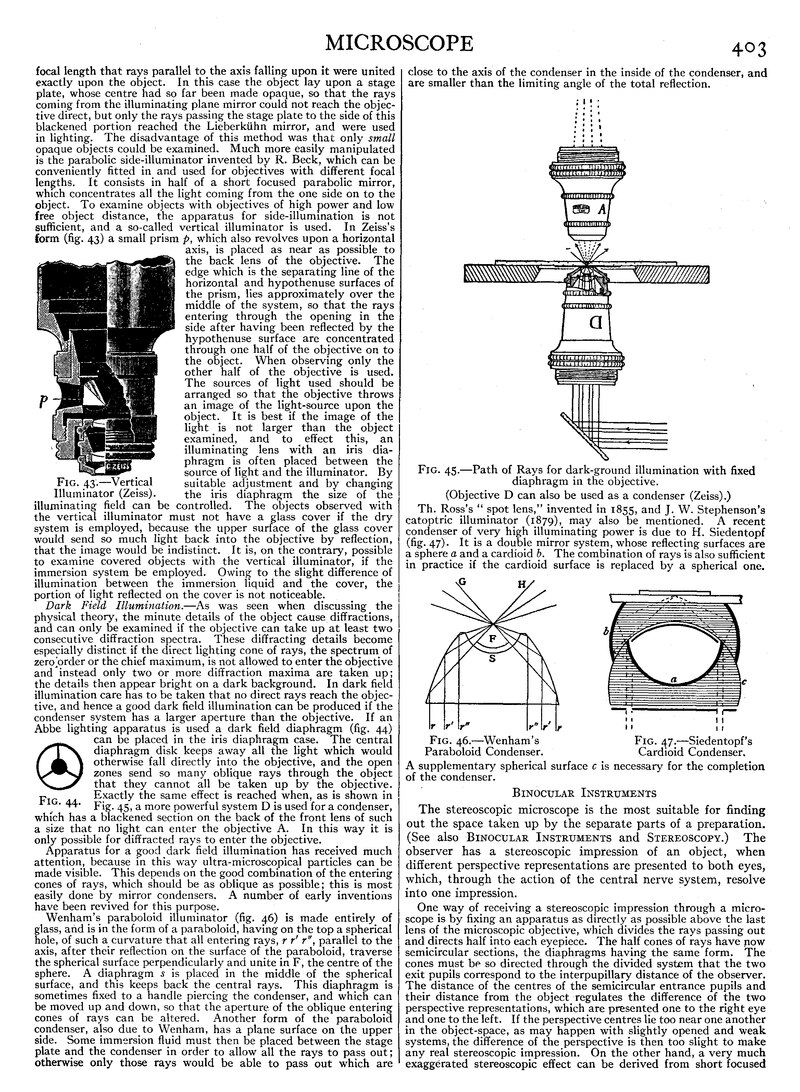
The disadvantage of this method was that only small opaque objects could be examined. Much more easily manipulated is the parabolic side-illuminator invented by R. Beck, which can be conveniently fitted in and used for objectives with different focal lengths. It consists in half of a short focused parabolic mirror, which concentrates all the light coming from the one side on to the object. To examine objects with objectives of high power and low free object distance, the apparatus for side-illumination is not sufficient, and a so-called vertical illuminator is used. In Zeiss's form (fig. 43) a small prism p, which also revolves upon a horizontal axis, is placed as near as possible to the back lens of the objective. The edge which is the separating line of the horizontal and hypothenuse surfaces of the prism, lies approximately over the middle of the system, so that the rays entering through the opening in the side after having been reflected by the hypothenuse surface are concentrated through one half of the objective on to the object. When observing only the other half of the objective is used. The sources of light used should be arranged so that the objective throws an image of the light-source upon the object. It is best if the image of the light is not larger than the object examined, and to effect this, an illuminating lens with an iris diaphragm is often placed between the source of light and the illuminator. By suitable adjustment and by changing the iris diaphragm the size of the illuminating field can be controlled. The objects observed with the vertical illuminator must not have a glass cover if the dry system is employed, because the upper surface of the glass cover would send so much light back into the objective by reflection, that the image would be indistinct. It is, on the contrary, possible to examine covered objects with the vertical illuminator, if the immersion system be employed. Owing to the slight difference of illumination between the immersion liquid and the cover, the portion of light reflected on the cover is not noticeable.
Dark Field Illumination.—As was seen when discussing the physical theory, the minute details of the object cause diffractions, and can only be examined if the objective can take up at least two consecutive diffraction spectra. These diffracting details become especially distinct if the direct lighting cone of rays, the spectrum of zero order or the chief maximum, is not allowed to enter the objective and instead only two or more diffraction maxima are taken up; the details then appear bright on a dark background. In dark field illumination care has to be taken that no direct rays reach the objective, and hence a good dark field illumination can be produced if the condenser system has a larger aperture than the objective. If an Abbe lighting apparatus is used a dark field diaphragm (fig. 44) can be placed in the iris diaphragm case. The central diaphragm disk keeps away all the light which would otherwise fall directly into the objective, and the open zones send so many oblique rays through the object that they cannot all be taken up by the objective. Exactly the same effect is reached when, as is shown in Fig. 45, a more powerful system D is used for a condenser, which has a blackened section on the back of the front lens of such a size that no light can enter the objective A. In this way it is only possible for diffracted rays to enter the objective.
Fig. 44. |
Apparatus for a good dark field illumination has received much attention, because in this way ultra-microscopical particles can be made visible. This depends on the good combination of the entering cones of rays, which should be as oblique as possible; this is most easily done by mirror condensers. A number of early inventions have been revived for this purpose.
Wenham’s paraboloid illuminator (fig. 46) is made entirely of glass, and is in the form of a paraboloid, having on the top a spherical hole, of such a curvature that all entering rays, r r ′ r ″, parallel to the axis, after their reflection on the surface of the paraboloid, traverse the spherical surface perpendicularly and unite in F, the centre of the sphere. A diaphragm s is placed in the middle of the spherical surface, and this keeps back the central rays. This diaphragm is sometimes fixed to a handle piercing the condenser, and which can be moved up and down, so that the aperture of the oblique entering cones of rays can be altered. Another form of the paraboloid condenser, also due to Wenham, has a plane surface on the upper side. Some immersion fluid must then be placed between the stage plate and the condenser in order to allow all the rays to pass out; otherwise only those rays would be able to pass out which are close to the axis of the condenser in the inside of the condenser, and are smaller than the limiting angle of the total reflection.
Fig. 45.—Path of Rays for dark-ground illumination with fixed
diaphragm in the objective.
(Objective D can also be used as a condenser (Zeiss).)
Th. Ross’s “spot lens,” invented in 1855, and J. W. Stephenson's catoptric illuminator (1879), may also be mentioned. A recent condenser of very high illuminating power is due to H. Siedentopf (fig. 47). It is a double mirror system, whose reflecting surfaces are a sphere a and a cardioid b. The combination of rays is also sufficient in practice if the cardioid surface is replaced by a spherical one.
| Fig. 46.—Wenham’s Paraboloid Condenser. |
Fig. 47.—Siedentopf’s Cardioid Condenser. |
A supplementary spherical surface c is necessary for the completion of the condenser.
Binocular Instruments
The stereoscopic microscope is the most suitable for finding out the space taken up by the separate parts of a preparation. (See also Binocular Instruments and Stereoscopy.) The observer has a stereoscopic impression of an object, when different perspective representations are presented to both eyes, which, through the action of the central nerve system, resolve into one impression.
One way of receiving a stereoscopic impression through a microscope is by fixing an apparatus as directly as possible above the last lens of the microscopic objective, which divides the rays passing out and dIrects half into each eyepiece. The half cones of rays have now semicircular sections, the diaphragms having the same form. The cones must be so directed through the divided system that the two exit pupils correspond to the interpupillary distance of the observer. The distance of the centres of the semicircular entrance pupils and their distance from the object regulates the difference of the two perspective representations, which are presented one to the right eye and one to the left. If the perspective centres lie too near one another in the object-space, as may happen with slightly opened and weak systems, the difference of the perspective is then too slight to make any real stereoscopic impression. On the other hand, a very much exaggerated stereoscopic effect can be derived from short focused systems of wide aperture. On account of the slight depth definition, short focused systems of wide aperture are not at all specially suitable for stereoscopic observation, because the possibility of observing objects taking up a good deal of space is too limited when such systems are used.

Fig. 48.—Riddell’s Prisms.
Professor J. L. Riddell (Quart. Journ. Micros, 1853, p. 236; 1854, pp. 18–24) published an arrangement of prisms, which, however, imparted a pseudomorphous impression if image-forming oculars were not used, and in 1854 a second system (fig. 48), 
Fig. 49. Wenham’s Prism.essentially a Wheatstone pseudoscope, added just above the objective. This gave an orthoscopic image even in ordinary eyepieces. By adopting right-angled reflection-prisms above the eyepiece he completely erected the image. Stephenson’s stereoscopic microscope (fig. 58, Plate) resembles this apparatus in all essentials. A construction of prisms by Nachet is now almost forgotten, while on the contrary an extremely simple dividing prism published by Wenham (Lond. Micros. Soc., 1861, i. 109) has been exceptionally well attested in practice. It is more easily used than any other apparatus (see Binocular Instruments, fig. 8). A reflection-prism (fig. 49) in a setting is placed above the last surface of the objective and divides the exit rays. The group of rays coming from the left half of the objective can continue its way without hindrance to the right eye. The group of rays coming from the right half of the objective is reflected twice in the
prism and directed to the left eye. The tube containing the left eyepiece is a little inclined towards the right tube, which is perpendicular. It can be adapted to the interpupillary distance by changing the tube slide. If it is desired to use the instrument as a monocular, the setting with the prism at the lower end of the tube is taken away.
A second manner of making stereoscopic observations employs stereoscopic eyepieces. The first of such eyepieces was proposed by R. B. Tolles.[2] He realized that the division of the cones of rays by prisms could only be satisfactorily performed if the prism was placed in the position of the exit pupil of the objective or in the position of the real image of this exit pupil. He employed a Nachet combination of prisms and placed the dividing prism at the spot where a special reversing system formed a real image of the exit pupil of the objective. A second stereoscopic eyepiece was devised by A. Prazmowski who substituted a Wenham diffracting division prism at the position of the real image of the exit pupil of the objective formed by a reversing system. The newest form of a stereoscopic microscope resembles the oldest in so far as two completely separate microscopes. are used. In the oldest microscope by Cherubin d’Orleans the observer receives a pseudoscopic impression in consequence of the reversed image. This defect has been avoided in the instruments constructed in the Zeiss factory (fig. 59, Plate) at the instigation of the American zoologist H. S. Greenough. The system of Porro prisms employed affords a convenient method of adapting the ends of the eyepieces to the interpupillary distance. The two tubes are inclined to one another at an angle of about 14°. The microscope is only intended for slight magnifications. The possibility already suggested of using both eyes for observing without having a stereoscopic impression, is often regarded as a great advantage. Binocular microscopes have therefore been constructed on this plan. Such a combination of prisms was used by Wenham, who placed it directly behind the last objective lens. As a rule this arrangement of prisms can be exchanged for the Wenham stereoscopic reflection-prisms.
 |
| Fig. 50. Powell’s Prisms. |
A second kind of dividing prism which directs the entire course of rays to both eyes, and thus produces identical images, was used by Powell and Lealand (fig. 50). Every ray is divided into a reflected and a refracted portion on the front side of a parallel plate. Whilst the refracted portion after leaving the plate continues its way in the same direction, displaced a little to one side, the reflected portion is directed into the side tube by a reflection-prism. With these microscopes, which are not stereoscopic, objectives of any power can be used. The surfaces of the dividing prisms must be very exact, so that no deterioration of the image may arise from them. A microscope for two eyes can also be by employing the Abbe stereoscopic eyepiece.
By the supplementary use of one of Wenham’s prisms every ray is analysed into a more powerful refracted and a weaker reflected one. The same image can be presented to each eye by using this eyepiece also. No stereoscopic impression is then felt. It is brought about by placing special semicircular diaphragms in the plane of the exit pupil of the microscope. By turning the diaphragms 180° round the optical axis, the orthoscopic impression can be changed into the pseudoscopic. The mechanical arrangement of the eyepiece is such that the distance of the two exit pupils can be adjusted to the interpupillary distance.
Mechanical Arrangements
Although the optical. system is the first consideration in a microscope, the system is valueless if the fittings do not allow its correct use. The optical system must be kept at a certain distance and well centred, and a correct position for the object in relation to the system must be assured.
In fig. 60, Plate, the microscope is seen to consist of the heavy metal foot A, which rests on the table at three points. The whole microscope is fitted to this foot. The object can be held firmly on the stage plate B by cramps C. On the lower side of the stage plate are the condenser and the diaphragms, and the illuminating mirror I is held by a rod D fixed to the stage plate. Likewise on the stage plate is the support for the tube E. The rough adjustment of the microscope can be made by a rack and pinion F; and the fine adjustment by the screw G. The tube containing the eyepiece and the objective is double. The inner tube H is movable, making a change in the length of the tube possible. As a rule this inner tube has a mark which allows the length of the tube to be set.
It is most important the stand should be free of vibration. A fine adjustment is also necessary, in order to perform conveniently and with certainty the slight motion of the microscope in relation to the object. In cheap stands the rough adjustment was worked by moving the inner tube by hand, but the more convenient rack and pinion is now used almost exclusively.
For slight magnifications rough adjustment is sufficient, but with objectives of a focus below 14 in., a fine adjustment is wanted. Very different constructions are in use. Almost all are such that the whole microscope tube is raised or sunk by the mechanism of the fine adjustment, and not only the objective. The most used is the micrometer screw adjustment (fig. 51).
 |
 | |
| Fig. 51.—Micrometer Screw Adjustment of Leitz. |
Fig. 52.—Lever Adjustment of J. Swift & Son. |
The tube carrier B fits closely on to a column A which is fixed firmly to the stage plate. The end of the column C is traversed by the micrometer screw D which is set in action by the knob E. The column A contains a powerful spiral spring, which exercises a strong pressure on the plate F fixed to the carrier B. By screwing in the micrometer, the spring is compressed and the tube lowered. By the contrary movement the spring pressure raises the tube as far as is allowed by the screw. The strong pressure of the spring practically excludes motion, which with fine adjustments is very important. Another very good adjustment is that of Messrs Swift & Son, shown in fig. 52. The long lever D is pressed to one side by the screw F, and is thus turned round the pin E. On the tube very near to the pin E is a cylinder C, which by the action of the screw F is very slightly raised, or lowered. A double lever is used in a fine adjustment by Messrs Watson & Sons (fig. 53). According to whether the screw A or B is used, the adjustment is fine or coarse. In other fine adjustments by means of springs and balance wheels either a micrometer screw is moved (Zeiss), or a curved disk fixed to the balance wheel is turned (Leitz), or an oblique disk arranged more or less in a circle and attached to the balance wheel is revolved (Reichert). These modern adjustments are made so exact that motions can be easily measured

| ||
| Fig. 57.—LARGE DISSECTING STAND (ZEISS). | ||
 |

| |
| Fig. 58.—STEPHENSON’S BINOCULAR MICROSCOPE (SWIFT). |
Fig. 60.—THE DEMONSTRATION MICROSCOPE (BAKER). | |
 Fig. 59.—GREENOUGH’S BINOCULAR MICROSCOPE (ZEISS). |
 Fig. 61.—PETROGRAPHICAL MICROSCOPE (ZEISS). |
up to 0·002 mm. An essential in all rough and fine adjustments is that the motion must always be parallel to the optical axis of the microscope, so that the same point in the object remains in the centre of the field.
Another condition which must fulfilled by a good stand is the power of inclination. It is only rarely necessary to arrange the preparation really horizontal; and for easy observation, especially when it will take a long time, ;it is of great assistance if the microscope can be inclined, so that the observations can be made in a natural position. The apparatus for inclining the microscope is chiefly such that the microscope can be placed in all positions between the vertical and the horizontal. The horizontal position is sometimes necessary if photographs are to be taken by the microscope.

Fig. 53.—Double Lever Adjustment
of Watson & Sons.
Many devices are available for changing the objective. It is essential that the objective is always brought before the lower end of the tube in such a way that the optic axis of the objective coincides with the optic axis of the rest of the system. The fittings of the objective and the changer are so arranged that little or no fine adjustment is necessary after the change. The most widely used is the revolving changer (fig. 60, Plate). The revolver may hold two, three or four objectives. In the sliding changer the objective is, dovetailed to a slide, the correct position being secured by clamps.
Fully equipped microscopes have apparatus for moving and turning the object. In simple microscopes the stage plate lies on the stand held by two springs, and must be moved by the hand (fig. 60, Plate). For elaborate work a so-called cross-table is indispensable. By means of screws the stage plate is movable in two directions at right angles to one another, in the plane of the stand. In many cases the stand is also movable round the optic axis.
The microscope stands described above can be used for the greater number of the naturalist’s experiments. For very special objects the stand must be expressly made; thus stands with tube carriers very much projecting are made for examining sections of the brain. The petrographical microscope is shown in fig. 61, Plate.
In order to determine the refractive index when the thickness of the crystal is known, or the thickness of the crystal when the index is known, a fine adjustment A makes it possible to measure exactly the changes in the length of the microscope. Further, a revolving stage plate provided with a graduation B is used to determine the angle in crystals. To obviate mistakes the optical axis of the microscope must coincide with the revolving axis of the plate, and the revolving plate has a central position C to keep this condition fulfilled. In many stands the objective can be centred instead of the plate. For measuring this angle, an eyepiece with cross-threads is used. In the lower focal plane of the eyepiece, at the spot where the real image which the objective forms of the object arises, a glass plate is introduced on which are two fine cross lines or even two very thin threads. The eye-lens can be adjusted for the thread-plate, so that different observers can see the cross clearly. The cross is always adjusted first. When observing with such an eyepiece, care must be taken that the real image of the object lies in the plane of the cross threads, i.e. that there is no parallax. The adjustment is easily controlled. If the eye is moved to and fro over the eyepiece and the image makes apparently similar movements in relation to the cross threads, then the image does not yet lie in the plane of the threads.
To measure the angle, the images of the crystal edges are covered in turn by one of the threads by turning the table, and the angle of rotation is read from the scale. A cross-table is very convenient for this calculation, for with the aid of the two movable slides situated in the plane of the plate and at right angles to one another, the point where the two crystal edges intersect can be quickly and correctly brought into the revolving axis of the plate. This measurement can also be made with a goniometer eyepiece, in which a row of parallel double-marks are used instead of the cross threads. The fitting of the eyepiece at the upper end of the tube is provided with a graduated circle. The eyepiece proper with the parallel strokes can be revolved, and the rotation be read from the graduated circle. In carrying out this calculation the marks of the thread-plate have only to be placed exactly parallel to the crystal edge.
For examining preparations in polarized light a polarizer D is introduced in the illuminating apparatus below the diaphragm and an analyser E above the eyepiece. The analyser can be rotated, the angle being read by a divided circle F. Very often the analyser is placed in the tube, a little above the objective: it is then generally in a case G, which can be put into the tube. The placing of the analyser near the objective has the advantage that the field of View is not restricted, as is the case if the analyser is used above the eyepiece. Nicols’s, Glan-Thomson prisms or similar polarization apparatus are used as polarizers and analysers. Below the analyser G a plate H of selenite or mica may be put in the course of the rays. This small plate can also be laid above the polarizer in the illuminating apparatus or in the eyepiece.
To examine crystals, especially in converging light, a condenser, movable in the optic axis, is needed above the polarizer. The image produced by the microscope objective M in its back focus plane is then observed through a supplementary microscope. The objective of this supplementary microscope, the Bertrand lens, can be applied through a window I at the lower end of the inner tube K. By using a rack and pinion movement L the supplementary microscope can be adjusted for the images. There is nearly always an arrangement to observe the preparation first in convergent light and then in parallel polarized light. This change can often be brought about by taking away or adding parts of the condenser.
Micrometry
It is often required in microscopical work to determine the size of objects or parts of objects.
There are three essential ways of performing this. The first method uses the objective screw micrometer. The object is placed on a slide in the plane of the stage plate and able to be very finely moved by the micrometer screw, which has as fine a worm as possible. A divided cylinder is fixed to the turning knob, which thus makes it possible to measure fractions of the revolution. The revolutions of the cylinder are registered by a calculator. The use of an eyepiece with a cross thread is essential to this measurement. After the microscope has been so adjusted that the image of the object to be measured falls exactly in the plane of the cross threads, the object is moved by the micrometer until one edge of the object is exactly covered by a thread. The micrometer is now read. Then the object is moved by the micrometer till the image of the other edge is covered by the thread in the eyepiece, and the micrometer is again read. The difference between the two positions gives the size of the object. The objective screw micrometer is, however, not sufficiently delicate, and is only used when comparatively large objects are to be measured, and especially for objects whose edges do not appear at the same time in the field of view.
The second and most widely used method employs a micrometer eyepiece. In this case not the object itself but a real image which has already been magnified by the objective is measured, and obviously much more accurate results are possible. The most accurate calculations are obtained by using the screw micrometer ocular (fig. 54).
Fig. 54.—Screw Micrometer Ocular. Sectional elevation and
plan (Zeiss).
Directly below the collective lens of a Ramsden eyepiece a slide b can be moved by a micrometer screw a; the slide carries a little glass plate c provided with a graduation. With the help of this scale the total revolutions of the screw can be read; fractions of the revolution can be read from the divided cylinder d. The scale is generally divided into hundredths of millimetres or thousandths of inches. A fixed mark which serves as an index is placed on the lower side of the collective lens and is seen clearly at the same time as the graduation of the movable slide. The micrometer stands at zero if the zero mark of the cylinder coincides with the index and the fixed mark is at a known division. The calculation is most convenient if the micrometer is left in the position of zero and the object is moved till one of its edges corresponds to the zero mark of the eyepiece scale. If the micrometer is then moved till another graduation corresponds to the other edge of the image the size of the image can be read off. As this method measures the image correctly to a few thousandths of millimetres, the object itself is measured accurately to some hundred-thousandths of millimetres, if it has been magnified a hundred times by the objective. To keep up this degree of exactitude the magnification of the objective must be carefully ascertained, e.g. by using an objective micrometer. A fine scale with known intervals is put on the stage plate, and by determining the distance between the graduations of the objective micrometer formed through the same objective, by means of the screw micrometer ocular, the magnification of the objective is determined. As the errors in the graduation of the objective micrometer are also magnified, very exact scales are necessary. When determining the magnification the microscope must be used under exactly the same conditions: neither the length of the tube nor the focal length of the objective may be altered. A fixed eyepiece micrometer is simpler and more popular. This consists of a scale on a little glass plate, which, instead of a cross wire, is placed in the eyepiece. The adjustment must be such that the image produced by the objective falls exactly in the plane of the scale. The size of the image is determined by calculating the entire interval taken up by it. By using an objective micrometer in place of the object, the magnification of the objective can be ascertained and from this the actual size of the object. As fractions of intervals can only be estimated in this method, a measurement with such an eyepiece scale can of course not be as exact as with a screw micrometer ocular. However, such a determination of size is often quite accurate enough.
A third method employs a drawing prism. The object and the drawing plane are seen at the same time and the outlines can be readily drawn. If, as before, an objective micrometer is placed below the microscope in the place of the object, and the size of a special micrometer-interval is drawn on the same board, then the actual size of the object can be ascertained. Instead of first drawing the object and the objective micrometer, they can of course be projected at the same moment on a scale on the drawing board. The errors attending the determination of the size of a microscopic object depend chiefly on the accuracy of the objective micrometer; any errors in the micrometer being magnified by the objective. These may be diminished by using different parts of the objective micrometer for the correction of the eyepiece scale, and the calculation of the size is based on the found mean value. A second error can arise through the inaccuracy of the eyepiece micrometer, and also in the case of a screw micrometer through periodic faults of the screw, and through dead motion. The eyepiece micrometer allows its errors to be diminished, if one measures at different points and then fixes a mean value. The dead motion of a micrometer screw is best avoided by working the screw always from one and the same side. The thickness of the cross wire may also occasion a fault. For this reason there is sometimes employed two very narrow threads lying beside one another, and which limit the image as nearly as possible.
The Testing of the Microscope
The excellence of a microscope objective depends on its definition and its resolving power.

Fig. 55.
DD =diaphragm.
K1K2=condenser.
L=front lens of the objective.
The lower figure shows the plan of the transmission.
The definition is better according as the chromatic and spherical aberrations are removed; there always remains in even the best constructions some slight aberration. In consequence of these residual aberrations, every object-point is not reproduced in an ideal image-point, but as a small circle of aberration. These circles will be objectionable when the smallest details are examined.
The size of these circles depends, in the case of equal tube lengths, only on the type of the objective, and not on the focal length, exact execution being assumed. Object details will only be well seen if the aberration circles are small in comparison. The size of these details in the image depends only on the magnification of the objective, M=Δ/f1′, and can by appropriate choice of the focal length of the objective be brought to the right value. In the case of a suitable ocular magnification, the details will be well seen, while the aberration circles remain invisible. It is therefore possible to judge the excellence of the focusing of objectives on the strength of the ocular-magnification, or the over-magnification, which they permit.
E. Abbe, through the so-called delicate ray transmission, suggested a way by which the quality of the images of objectives can be observed. The ray transmission, shown in fig. 55, is obtained by means of a stop of the form shown in the lower figure and placed under the condenser in the plane of the iris diaphragm. The entrance pupil is in this way reduced on two small separate fields, which nevertheless contain rays of all zones. It is necessary that the outside edge of the diaphragm coincides with the edge of the entrance pupil. This can be attained by drawing the iris diaphragm so far as to form the entrance pupil. The double diaphragm is then in such a position that the edge of the outer diaphragm coincides with the edge of the iris diaphragm.
The object employed must have distinct boundaries. Abbe’s test plate consists of an object carrier on which six cover glasses of exactly determined thickness (between 0·09 mm. and 0·24 mm.) are cemented. The cover glasses are silvered on their under surfaces, and in the silvering fine lines are drawn; these lines form the test object. This plate admits at the same time of a correct determination of the thickness of the cover glass, for which the best correction exists. So long as the object is not sharply focused two separate dispersion figures will be seen. 'The defects of the objective are revealed, e.g. two adjacent sharp images are formed, which become indistinct if they coincide, or one pencil produces a distinct, the other an indistinct image, or that the images are surrounded with coloured rings. Owing to the curvature of the image, all parts of the object are not seen distinctly at one and the same time.
The resolving power of an objective depends on its numerical aperture. The numerical aperture can be determined in two ways. A diaphragm with a very narrow hole is placed on the stage, and the microscope sharply focused on the edges of the hole. The illuminating mirror is turned aside and a graduated scale is laid on the foot of the microscope. Strong systems produce in the proximity of their back focal plane an image of the scale, which can be inspected with a weak auxiliary microscope, and the length of the visible part of the graduation determined. The ratio of half the length of the visible piece of the scale to its distance from the diaphragm on the stage gives the tangent of half the angular aperture. The sine of this angle is the numerical aperture for dry lenses. With weak systems no auxiliary microscope is necessary, the eyepiece being removed and the scale viewed directly in the tube.
E. Abbe constructed a simple instrument for the determination of the aperture, termed the apertometer (fig. 56). A semi-circular glass plate bears two scales, over which two black thin metal plates bent back at right angles may be moved.
Fig. 56.—Abbe’s Apertometer (Zeiss).
A little hole in the silvered plate a marks the centre of this circle. Through this hole the points of the metal plates b can be observed by total reflection on the surface c. The apertometer is laid on the stage, so that the hole lies in the axis of the microscope, and the hole is sharply focused. The eyepiece being removed the image of the metal plates b produced by the objective is seen. In order to ensure for the eye a central position, there is fixed on the upper end of the tube in place of the eyepiece a disk of pasteboard or metal with an axial hole. The metal plates b are then moved till the points just cut off the edge of the field to be surveyed. The angular or numerical aperture can then be read off. With strong systems the vanishing of the points is observed with an auxiliary microscope, formed by means of the inner tube. In immersion systems the immersion liquid is placed between the front lens and apertometer.
If the numerical aperture be known the resolving power is easily found. The resolving power can also be determined by using different fine test objects. Norbert’s test plates, which bear graduated groups of extremely fine and narrow divisions are very useful, while the tests of Amphipleura pellucida and Surirella gemma are often employed.
The magnification of a microscope is determined from the focal lengths of the two optical systems and the optical tube length, for N=250 Δ/f1′f2. To determine the optical tube length A, it is necessary to know the position of the focal planes of the objective and of the ocular. If one focuses an auxiliary microscope, carried in the inner tube, on the image situated in the back focal plane of the objective of a distant object, and then on the dust particles lying on a slide pressed against the end of the outer tube, the displacement of the auxiliary microscope gives the distance of the back focal plane of the objective from the end of the outer tube. To determine the position of the anterior focal plane of the eyepiece, the eyepiece is placed on the stage with the eye-lens downwards. An auxiliary microscope is now focused first on the image of a distant object and then on the plane of the edge of the setting. This plane can be marked by a small piece of paper. This gives the distance of the anterior focal plane of the eyepiece from the bottom edge of the setting of the eyepiece and consequently also of the edge of the eyepiece carried by the upper end of the tube. These measurements determine the optical tube length Δ.
There are many methods for determining the focal length of the objective. The objective to be examined is placed on the stage, and in the manner just shown, the distance of the focal plane from the edge of the fittings or to the surface plane of the front lens is determined. Any plane object a few yards distant can be used. If the object can be seen by using the mirror, the plane mirror must be used; then the actual size of the object and of the image produced by the objective is measured (of the image by a micrometer ocular). The distance of the object from the nearer focus of the objective is next determined. This distance is composed of the distance of the object from the centre of the plane mirror, and of the distance of the focus of the objective on the stage plate from the centre of the plane mirror. Let the size of the object be y, the size of the image y ′ the distance of the object from the focus x, then y/y ′=x/f1 from which f1 can be calculated (see Lens). The same method can be used to determine the focal length of the eyepiece. These are the dimensions necessary for determining the magnification of the microscope, viz. the optical length of the tube Δ, the focal lengths of the objective f1′, and of the eyepiece f2.
The focal length of an objective can be more simply determined by placing an objective micrometer on the stage and reproducing on a screen some yards away by the objective which is to be examined. If the size of the image of a known interval of the objective micrometer is determined by an ordinary scale, and the distance of the image from the focal plane of the objective belonging to it is measured, then the focal length can be calculated from the ratio y/y ′=f1′/x1′, in which y is the size of the object, y ′ that of the image, and x1′ the distance of the image from the focal plane belonging to it.
Besides this indirect method of determining the magnification there is also a direct one, in which it is not necessary to first measure f1, f2 or Δ. If a drawing prism is used above the eyepiece, and an objective micrometer is inserted, then if a scale is laid on the drawing board which is 25 cm. distant from the exit pupil, one or more intervals of the objective micrometer can be seen projected on the scale lying on the board. The comparison of the two scales gives directly the magnification. The course of the light within the drawing prism must be taken into account when determining the distance of the scale from the exit pupil. Although this method does not give very accurate results, it is more convenient and simple than the indirect method.
Bibliography.—E. J. Spitta, Microscopy (2nd ed., 1909); Sir A. E. Wright, Principles of Microscopy (1906); W. B. Carpenter, The Microscope and its Revelations (8th ed. by W. H. Dallinger, 1901); J. Hogg, The Microscope (15th ed., 1898); H. van Heurck, The Microscope (Eng. trans. by W. E. Baxter, 1893). W. Kaiser, Technik des modernen Mikroskopes (Vienna, 1906), deals with the practical aspects, whilst the theory is treated in M. von Rohr (Die Theorie der optischen Instrumente, Berlin, 1904) and in S. Czapski (Grundzüge der Theorie der optischen Instrumente; ed. by O. Eppenstein, Leipzig, 1904). (O. Hr.)