or castings, which are known as the stem at the fore end, and the
stern-frame or sternpost at the after end. The stem of a warship
is generally made very massive, and projects under the water so
as to form the ram.
| Fig. 75. |
The longitudinal framing is carried right forward and aft when possible, and the ends of the several frames are connected together across the ship by strong plates and angles, which are called knees or breasthooks, forward; and knees or crutches, aft. Additional supports, introduced to enable the vessel to withstand the heavy blows of the sea in bad weather, are called panting stringers, panting knees, and panting beams, panting being the term applied to the movements which occur in the side plating if sufficient strength is not provided. Where the ends of the ship are very full, or bluff, the frames are sometimes inclined, or canted out of the transverse plane, so as to be more nearly at right angles to the plating; such are known as cant frames. At the stern a transverse frame, called a transom, is attached to the upper part of the stern post to form a base for cant frames of the overhanging part of the stern which is known as the counter. To assist the beams and bulkheads in holding the decks in their proper positions, vertical pillars are introduced in large numbers; but to avoid the loss of space and inconvenience in handling cargo, ordinary pillars are often dispensed with, and special pillars and deep deck girders are fitted instead.
The steel generally used in shipbuilding is known as mild steel. It is very tough and ductile, and differs from the hard steel, out of which tools are made, in that it will not take a temper, i.e. if heated and plunged into oil or water, the sudden cooling has very little effect upon it, whereas with tool steels a great change takes place, the steel becoming very hard, and usually brittle. This quality of tempering depends chiefly on the amount of carbon in the steel, mild steel containing less than ·25%. Steel of greater strength than mild steel is used occasionally in certain parts of warships. The extra strength is obtained generally by the addition of carbon, nickel or chromium, coupled with special treatment. The quality of the plates and bars used is tested by cutting off strips about 2 in. wide, and bending them double by hammering, or in a press, until the bend is a semicircle whose diameter is three times the thickness of the strip. The stri s are sometimes heated and plunged into water to cool them suddenly before bending, and they may be cut from either side or the end of the plate. Strips are taken occasionally and hammered into various other shapes while hot and while cold, so as to ascertain the general quality of the material. To ensure its tenacity, strips are taken and machined to give a parallel part about 2 in. in width, of at least 8 in. in length. Two centre punch marks are made 8 in. apart, and the strip is secured in a testing-machine constructed so that the ends can be gripped by strong jaws which do not injure the parallel part. The jaws are then gradually pulled apart, the amount of the pull required to break the strip being registered, and also the extent to which the strip stretches in the length of 8 in. before breaking. The tensile strength varies between 26 and 32 tons per square inch, calculated on the original sectional area of the parallel part before breaking, and the elongation in the 8 in. is about 20%. The standard strength and elongation required by the principal registration societies have already been given. The steel used for making rivets is similarly tested; and samples of the finished rivets are also taken, and hammered into various shapes, hot and cold, to ensure that the metal is soft and ductile and suitable for the work.
The stem, stern-frame, &c., are frequently made of forged iron; but if of steel, they are cast to the form required. These castings are tested by being let fall on hard ground and then slung in chains and hammered all over, when faults of casting are generally discovered by variations in the sounds produced. By this hammering the general soundness of the casting is ensured. To test the quality of the steel in the casting, small pieces, which are cast on for the purpose, are removed and tested in the same manner as just described for the strips cut off from the plates; they are required to give about the same tensile strength, but a little less ductility, say 10% instead of 20% elongation in 8 in.
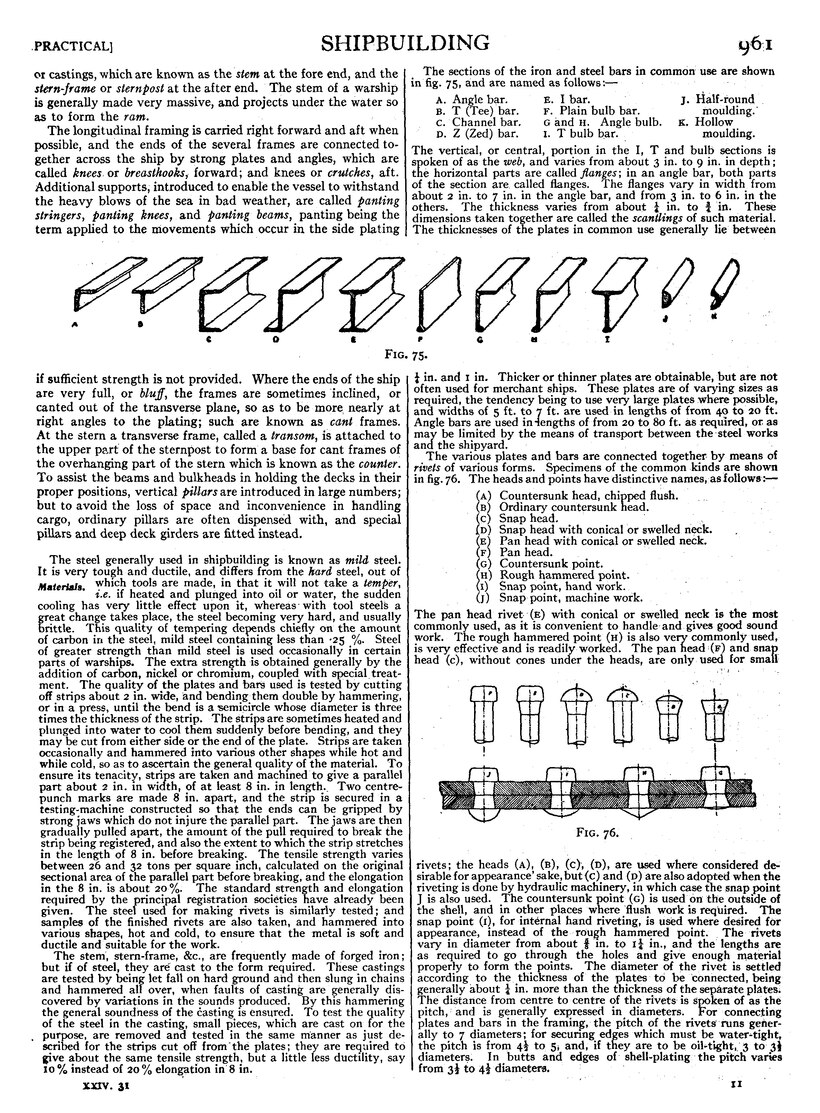
The sections of the iron and steel bars in common use are shown in fig. 75, and are named as follows:—
| A. Angle bar. | E. I bar. | J. Half-round |
| B. T (Tee) bar. | F. Plain bulb bar. | moulding. |
| C. Channel bar. | G and H. Angle bulb. | K. Hollow |
| D. Z (Zed) bar. | I. T bulb bar. | moulding. |
The vertical, or central, portion in the I, T and bulb sections is spoken of as the web, and varies from about 3 in. to 9 in. in depth; the horizontal parts are called flanges; in an angle bar, both parts of the section are called flanges. The flanges vary in width from about 2 in. to 7 in. in the angle bar, and from 3 in. to 6 in. in the others. The thickness varies from about 14 in. to 34 in. These dimensions taken to ether are called the scantlings of such material. The thicknesses of tie plates in common use generally lie between 14 in. and 1 in. Thicker or thinner plates are obtainable, but are not often used for merchant ships. These plates are of varying sizes as required, the tendency being to use very large plates where possible, and widths of 5 ft. to 7 ft. are used in lengths of from 40 to 20 ft. Angle bars are used in lengths of from 20 to 80 ft. as required, or as ma be limited by the means of transport between the steel works and the shipyard.
The various plates and bars are connected together by means of rivets of various forms. Specimens of the common kinds are shown in fig. 76. The heads and points have distinctive names, as follows:—
(A) Countersunk head, chipped flush. |
| Fig. 76. |
The pan head rivet (E) with conical or swelled neck is the most commonly used, as it is convenient to handle and gives good sound work. The rough hammered point (H) is also very commonly used, is very effective and is readily worked. The pan head (F) and snap head (C), without cones under the heads, are only used for small rivets; the heads (A), (B), (C), (D), are used where considered desirable for appearance’ sake, but (C) and (D) are also ado ted when the riveting is done by hydraulic machinery, in which case the snap point J is also used. The countersunk point G is used on the outside of the shell, and in other places where flush work is required. The snap point (I), for internal hand riveting, is used where desired for appearance, instead of the rough hammered point., The rivets vary in diameter from about 58 in. to 114 in., and the lengths are as required to go through the holes and give enough material properly to form the points. The diameter of the rivet is settled according to the thickness of the plates to be connected, being generally about 14 in. more than the thickness of the separate plates.
The distance from centre to centre of the rivets is spoken of as the pitch; and is generally expressed in diameters. or connecting plates and bars in the framing, the pitch of the rivets runs generally to 7 diameters; for securing edges which must be water-tight, the pitch is from 412 to 5, and, if they are to be oil-tight, 3 to 312 diameters. In butts and edges of shell-plating the pitch varies from 312 to 412 diameters.
